
Bravia XR-75x95J No Picture but has Sound (No red light blinking)
Issue: My XR-75X95J Power-ON AFTER plugging the TV into wall socket the TV will display SONY logo and then goes fully black.
Notes: A) The remote can still power on/off the TV.
B) Pressing the up/down/select of the remote causes the normal sound to happen.
C) There are no cables connected to the TV except for the power cable.
D) We attempted to connect a PS4 for troubleshooting to the HDMI port and tried to get the TV to acknowledge a separate input source, but it did not. All troubleshooting performed with nothing plugged into the TV.
E) Turning the TV OFF/ON while connected to the wall socket after the initial POWER-ON from plugging the TV into the socket results in no SONY logo appearing (the screen remains black).
F) There are no blinking red lights. The normal white light appears during the POWER-ON phase.
Troubleshooting steps performed:
1) We power cycled the TV: (waited 2 minutes, 2 hours, 8 hours) and then tried plugging in the TV.
2) We power cycled the TV with soft reset: after disconnecting from the wall (waiting 2 minutes, 2 hours) and then holding down the (single) power button on the TV for 60 seconds with the power cord UNPLUGGED, we then plugged the power cord back in without holding down the power button on the TV.
3) We tried to factory reset the TV by unplugging the power cable, waiting (2 minutes, 2 hours, 8 hours) and then holding down the TV power button while simultaneously plugging the power cord back into the wall. This produces the same SONY logo and then sometimes shows a multi-colored hollow circle on the screen with the word "Erasing" after which the TV goes black. Sometimes the TV power cycles twice during this sequence and sometimes it does not. The end result is the same, the TV only shows the SONY logo and then goes to a full black screen.
4) We downloaded the firmware from the SONY website for this model: v6.7612 as well as v6.8092. We formatted a USB stick as FAT32/32 and named the USB stick "SONY UPDATE". We then loaded the v6.7612 files (.zip and .dep) that we extracted from the SONY zip and performed the steps listed on the SONY website (https://www.sony.com/electronics/support...) for a firmware update. This was attempted multiple times with the screen never displaying anything. On one of the attempts the pilot light on the TV DID blink white on/off for several seconds but on that attempt we left it for 12 hours and the results were the same as all previous troubleshooting steps. On all other attempts there was no blinking/pairing indicator on the pilot light. After each failed attempt we also tried a power cycle and then a factory reset. Note that the files were correctly placed in the root directory of the flash drive, and after each attempt we completely deleted the flash drive and reformatted it before once again copying over the 2 files provided in the SONY zip.
5) We repeated step #4 with the v6.8092 firmware files downloaded from SONY.
6) We repeated steps #4 and #5 using a USB stick formatted for FAT32/16.
7) We once again tried a power cycle, soft reset and factory reset.
8) Periodically during the above steps we used a flashlight to look at the TV once it went black after the SONY logo went away. There was never a faint picture showing, it was completely black.
9) We opened up the back of the TV, checked capacitors on all boards and found no bulging.
10) We disconnected all cables on the back of the board and checked for oxidation (everything looked shiny/clean with gold/silver connectors). We blew down everything and the boards while unplugged using compressed air.
- The POWER-ON following the above produced a working TV that was at the Factory-default screen. We went through the initialization process, got to the Home screen and updated the software using the on-screen Settings selection process. The TV successfully powered ON and OFF several times using the remote. Apps worked.
- To verify everything was good before putting the back on, I turned OFF the TV using the remote and then unplugged it from the wall overnight.
- The following morning the situation was back to square 1: Initial Power-ON showed the SONY logo and then screen goes completely black. No flashing red light (just normal white light acknowledging Power-ON). Sound working (beep selecting things etc).
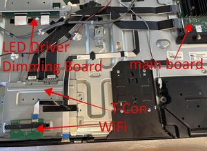
I have the repair manual but it doesn't seem to have diagrams for any board other than the mainboard and I'm trying to get to 'next steps' in the troubleshooting process. I'm having trouble telling what each of the cables is that connects the boards (that are not Pin cables) as well as figuring out what to check based on Page 45 of the Manual (No Picture flow diagram).
What I know for certain is that it's not a backlight issue. It seems like it might be related to the cables OR could be related to the Mainboard, T-con or 4th board that isn't the the above or Powerboard (don't know what its called).
Update:
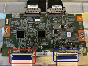
So I went and disconnected both LVDS cables from my TCON and that caused the backlights to come on and stay on after Power-ON. The screen stayed in a test pattern cycle (colors, black, white, grid) that was fully displayed across the whole screen.
Then I disconnected the power and reconnected the larger (right hand side) LVDS cable and then reconnected power and the screen went to the SONY logo at Power-ON and then turned completely off (no backlights).
Then I disconnected the power and Right LVDS cable and reconnected the smaller (left hand side) LVDS cable and then reconnected power and the backlights came on and stayed on. The full screen once again went into the same test pattern cycle as described above with both cables removed.
Throughout all of this the remote up/down produced sound.
So next steps? It seems like this points somewhat conclusively to a T-con board failure or something wrong with that LVDS cable (or the physical cable connector on either the Tcon or Mainbaord. Suggestions?
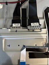
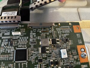
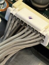
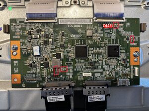
Pics below of Tcon cables with Right side disconnected.
Update 2
So I don't know how I can remove the plate covering the T-con because I dont see any way to remove these two cables? There is nothing on the sides to press, nothing on top that flips up, and pressing down on them seems like it will break the boards? Both of these are attached over the plate as seen below and above.
Update 3
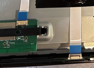
I still can't remove the ribbon connector to the wifi board and I may have stripped the IR sensor ribbon cable pulling it out ... sigh, but I did get the plate off.
Seems like the right LVDS cable connector has some visible damage on top? Everything else looks ok I think? Again, not sure on next steps other than to replace the board? And possibly cable?
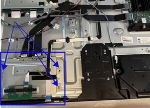
Update 4:
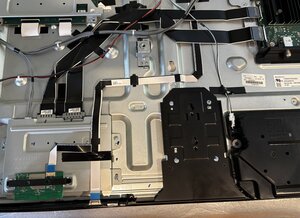
So with everything plugged in except the (blue square) ribbon cable that connects the Tcon to the LED board, my system powered-ON and had the backlights come up for a few seconds (like when the SONY logo appears) and then all turned off (full black). Repeating the process with only the (red square) ribbon cable connected produced the same results. I should note in both attempts the small ribbon cable that goes from my mainboard to (what I thought was the IR board/sensor) on the bottom center of my case [bottom right cable in the picture directly above my Update 3 above] was unplugged since it runs over the TCON, but my remote still worked so not sure what that connection does?
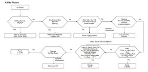
Update 5:
So I don't know how to locate any of the referenced connectors/voltages to check per the diagram? (updated picture from manual)
My mainboard looks like:
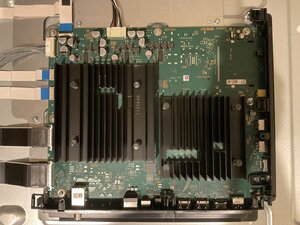
There is no callout anywhere on it for CN1700, CL451, or any of the listed connections in the flow diagram.
The wired connection from the power board (in upper left of mainboard pic above) is 2 rows of 10 but I have no idea how to tell which subslot would correspond to which of the 20 numbers in the manual diagram above? Also the back of the connector on the mainboard has a single 'pin/line' that goes down into the mainboard for each 2 wire slots (vertically connected) so I don't know how its possible to check a SINGLE wire slot? Also (if that is the connection referenced in the diagram) the wired connections dont have room to insert anything like a multimeter that I can see?
Additionally I don't see any way to tell which area of my mainboard is the hot side? So I'm very hesitant to touch it with a multimeter until I can understand that.
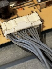
Update 6:
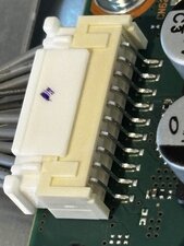
To better show what I'm referring to above, here is the connector on the mainboard that the powerboard wiring goes into. 20 wires in, in 2 rows of 10. Single connection in the back per each column of 2. No way to get anything (no matter how small really?) into where the wires comes in.
UPDATE #7:
So I was able to get a multimeter and needle probe to check SOME of the connections listed in the No Picture troubleshooting. This was done while the screen was in the failed state (no backlights illuminated, no picture).
On the Mainboard connection I checked:
TCON_24_ON and TCON_12_ON and both read 3.35 V. Based on the No Picture flow diagram this would mean I need to replace the TCON correct?
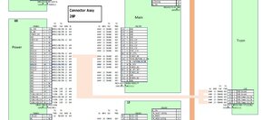
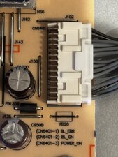
Further checks done for more information I checked the CN6401 (Power Board source of the cable connection to the Mainboard/Tcon. Pictures below. I BELIEVE I was able to check connection ports 1, 2, and 3 which correspond to BL_ERR, BL_ON, and Power_ON according to the more comprehensive Connection Diagram below from the Manual.
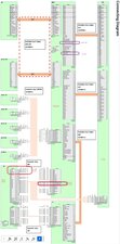
If you could confirm that the connection line in the upper RIGHT (top row right hand side) is line #1, and the one below it is Line #2 then I can confirm the following:
BL_ERR = 3.4 V
BL_ON = 0 V
Power_ON = 3.4 V
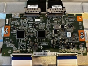
Furthermore, based on the full Connection Diagram picture I posted, I was looking for the other elements called out in the following step of the No Power flow chart: checking FE_PANEL_POWER_ON (CL445), BL_ON (CL446), AC_DET_FE_OR_BE (CL447), EVDD_DET (CL448), and TCON_INT_ERR (CL449). I found two of those listed in the Connection Diagram (I circled them in purple above) but they are part of the LVDS cable connection cable and I have no idea how I can check them with a multimeter? Unless the TCON board designations for C445 - C449 (which I believe are capacitors and not Voltage/connections?) Can you confirm based on the TCON picture below with the C44x circled?
Again, I dont think I necessarily need to do the above step since I found that the TCON_24 and _12 have voltage > 3V, per the No Picture flow chart it says to replace the Tcon right?
Update #8
I was able to order a refurb T-con and test it out today. Unfortunately when I switched to the new board my issue persisted (with some small differences).
So with everything plugged in the backlights came on and stayed on but there was nothing displayed. The PowerBoard output was:
BL_ERR = 3.4 V
BL_ON = 0 V
Power_ON = 3.4 V
And the MainBoard in from the PowerBoard showed:
Tcon_12 and Tcon_24 both = 3.3 V.
Repeating the process with only the (blue square) T-con ribbon cable connected resulted in the backlights coming up for a few seconds and then the screen went completely black. The voltages remained the same as described directly above.
Repeating the process with only the (red square) T-con ribbon cable connected resulted in the backlights coming up and staying on but with nothing displayed. The voltages remained the same as described directly above.
Throughout all of this I should note that 1) the remote continued to work and the sound beeped when pressing up/down, and 2) the small ribbon cable that runs over my T-con to plug into the bottom center of my TV was disconnected (since I still don't know how to unplug the other prong of that cable from the small circuit board it is attached to.
As a followup confirmation question I understand where the Tcon_12 and Tcon_24 connections are in the right of the snipped picture below of the manual NoPicture flow diagram. However I still don't understand where the CL445-CL449 connections are that are referenced on the left hand side of the picture.
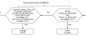
Are CL445-CL449 supposed to be on the Tcon board or the MainBoard? If they are supposed to be on the Tcon board all I can find are the C445-C449 (circled in red below) on the Tcon board. I can't find anything like that on the Mainboard.
Also, the NoPicture flow diagram shows the result of Tcon_12 and Tcon_24>3V to be "Panel (T-con)" are these two separate things (i.e. Panel = LED Panel Board, and T-con = T-con) or is the diagram just calling the singular T-con board "Panel (T-con)". I'm wondering if my next step here is to replace the LED board but I still don't understand how my PowerBoard output for BL_ON = 0 for every condition even when the backlights are all lit up?
Update 9/27/2025
I have now replaced both the 41p and 51p connection cables that run between the mainboard and the Tcon (called "V by One FFC Harness" CN 6800 and 6801 in the manual's 4.0 No Picture flow diagram. I have tried replacing them one by one and then together and the result is the same: no change in result. I have also tried this with both Tcon boards I possess and there is no change. The TV still powers on, the backlights come on for a few seconds and then go off completely. TV still responds to remote and sound still works. Any further ideas anyone? I still have no idea what CL44x are supposed to be from my questions from update #8 directly above. I'm about ready to just kill myself here.
crwdns2934109:0crwdne2934109:0

crwdns2944067:06crwdne2944067:0
@caig64685 you can't disconnect since you will need this operational for the voltage measurements. You need some very small probes ( I have a set with needle soldered to the tips to test those), Check your other boards and do not forget to the LED driver board. It looks like the ribbon cable from the main board to the LED driver board is on the connector that you are looking for. ON your posted images I can only identify some of the connector markings on the T-con board.
crwdns2934271:0crwdnd2934271:0 oldturkey03 crwdne2934271:0
@caig64685 if you do not have any fitting probes you will have to measure it on the contacts. The ones you see are for the top row. To measure the bottom row, you will have to remove the board and measure from the bottom. Makes things complicated sine you will have power on the boars and all the cables connected. If you have probes small enough you can insert those in the same area as the wires go into on the connector. Have you checked The LED driver board yet? Anything odd on that?
crwdns2934271:0crwdnd2934271:0 oldturkey03 crwdne2934271:0
@oldturkey03 Thanks again for all the help on this. I was finally able to get needle probes yesterday and get the next phase of checkout done. I think this gives me my answer? But I'm definitely still stumped about a couple of things I posted in my Update #6 if I was forced to check the signals from the next part of the No Picture troubleshooting flow diagram.
crwdns2934271:0crwdnd2934271:0 Caig crwdne2934271:0
@caig64685 yes, according to the flowchart the offending board would be your T-con board. Replace it and re-evaluate.
I can not yet confirm the way the contacts are labelled. It is more common that they go in rows. i.e 1 -10 on top 11-20 on bottom.
crwdns2934271:0crwdnd2934271:0 oldturkey03 crwdne2934271:0
@caig64685 CL451 and CL452 are connector pins and should be coming from the main board. Your BL_On signal should also come from the main board. You can check your LED driver board but since your backlights come on (with pulled cables etc.) it does not sound like the issue here.
crwdns2934271:0crwdnd2934271:0 oldturkey03 crwdne2934271:0
crwdns2934273:01crwdne2934273:0