

Samsung QLED Power supply defect
Dear Forum,
My Samsung QLED
GQ65G70TGTXZG
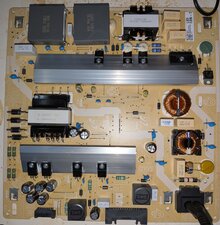
Power supply: BN44-01063A
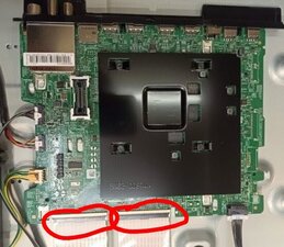
Mainboard: BN41-02749A
is completely dead. The standby LED does not light up.
Up to the MOSFETs on the primary side the voltage is fine. In the high-frequency section I cannot measure. On the secondary side there are no DC voltages measurable. I suspect the switching power supply controller is defective, but I cannot find any schematics and at this point my skills are also at their limit. The entire power supply is available as a spare part, but I want to make sure that the mainboard is not damaged.
Therefore, I applied the standby voltage using a lab power supply with current limit set to 0.1A. The standby LED now blinks and I can hear a clicking sound from the mainboard. I would assume this behavior is to be expected – or am I mistaken?
Thank you very much for your opinion!
Best regards,
Andreas
Update (09/03/25)
Hi all,
I installed the new (used) power supply. Unfortunately, that only solved part of the problem.
I fear whatever damaged the PS also damaged the Mainboard or Display.
Here’s what happens:
The standby LED lights up.
The TV seems to try to start: the backlight briefly turns on, and sometimes the startup melody can be faintly heard.
Then the startup process stops and starts over again – an endless loop.
Interestingly, if I unplug one of the two ribbon cables on the mainboard, the backlight stays on, the startup melody plays completely, and the TV even shows up in the list of Bluetooth devices. However, it doesn’t matter which cable I disconnect – the behavior is identical in both cases.
Does anyone have an idea what could be causing this?
Best regards
Andreas
crwdns2934109:0crwdne2934109:0


There is no standby voltage measurable. It seems that the standby voltage should be 7.5V (there is no specification given on the board). When the TV is switched on the standby voltage is increased to 13V.
At 7.5V supplied by the external PS the power on led lights up constantly. When I press the power on button the power pin is at 3V for some seconds. The clicking sound appears only at about 13V as if the Mainboard tries to start up but can't due to the current limit. I think the Mainboard is ok, therefore I ordered a used PS board.
Thanks
Andreas
crwdns2934271:0crwdnd2934271:0 Andreas B crwdne2934271:0
@andreasb41819 that is the right thing to do. No standby voltage is (almost) always based on a bad power board. Since schematics are not available and there is no obvious damage, it's definitely easiest to replace the PSU. Let us know how it works out.
crwdns2934271:0crwdnd2934271:0 oldturkey03 crwdne2934271:0
@andreasb41819 where do you disconnect the ribbon cables? Right at the main board? Where do they lead to? A T-con board or to the buffer boards on your LCD?
crwdns2934271:0crwdnd2934271:0 oldturkey03 crwdne2934271:0
Sorry, I forgot to attach the photo.
After further research, I suspect a defect in the panel or the buffer board, although I cannot rule out a faulty T-Con board.
It seems that during the startup sequence, the display’s status is checked. If the LVDS cable is disconnected, the display is not activated at all – therefore, the boot loop does not occur.
However, if both cables are connected, the display is activated. Due to a short circuit, the TV then shuts down and restarts.
This is my theory so far: If it’s correct, I might be able to locate the short circuit by selectively taping off individual pins and/or measuring the capacitors on the buffer board.
Has anyone had experience with using a thermal camera to find such faults? The TV shuts down very quickly, so the components have very little time to heat up.
I would really appreciate any professional advice.
Thank you very much and best regards,
Andreas
crwdns2934271:0crwdnd2934271:0 Andreas B crwdne2934271:0
I attached the photo to the original post. The T-Con is integrated on the Mainboard. The ribbon cables lead to buffer boards.
crwdns2934271:0crwdnd2934271:0 Andreas B crwdne2934271:0
crwdns2934275:02crwdne2934275:0