crwdns2933423:0crwdne2933423:0

The Nintendo Switch is a handheld game console that can be played on the TV via a docking station, or on the go. Released March 3rd, 2017.

Dark LCD, Image Retention, Circular backlight - Heat Damage?

Hi there, this switch seems to have some display issues which I am wondering if someone could help me with. I am planning to open it up this weekend but I would like some prior guidance if possible.

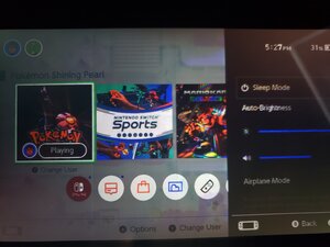
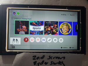
In handheld the brightness is on max but the screen is still very dark. There only seems to be proper backlighting in the very middle circle of the screen?

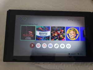
When the console is playing games everything is very very dark as shown below with Pokemon. There is also a very solid image of whatever has been running for a few minutes prior overlaying everything as well

Apparently, the switch was left in standby in a blanket for a long duration.

From what I can guess it seems like it may be damage from overheating and some major burn in? Would this be an LCD replacement or could I possibly fix this by re-seating a ribbon cable?

Thanks for the help.

---------------------------------------------------------------

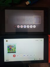
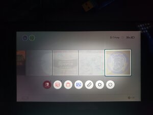
This is a comparison with a normal switch:

Block Image

Pokemon, on max brightness:

Block Image

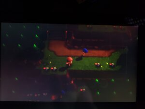
Burn in? After running Pokemon for 2 minutes:

Block Image
Block Image

Update 1:

I have a working console, and swapped the LCDs both ways. All screens appear broken in the bad console and all seem to work in the normal console. So I do not think it is a LCD Issue.

'Broken' Screen - Working Switch:

Block Image

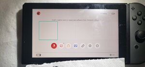
Working Screen - Broken Switch:

Block Image

'Broken Screen' - Broken Switch:

Block Image

Update 2:

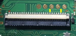
I looked into the LCD connector. Visually it looks fine to me but I did find some differences compared to my working console using diode mode on a meter.

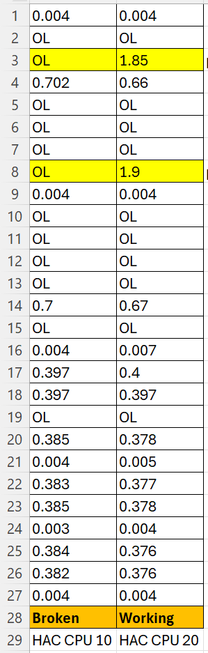
The 3rd and 8th pin seem to be OL instead of ~1.9v.

Block Image

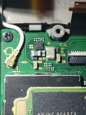
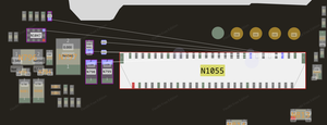
I found a board view file of the motherboard and followed the pins back to this cluster, but I cannot find what this area is for yet, besides from it 'being for the LCD' . I checked all the passive components in the area and they all seem the same on both consoles. I also began testing the chip but I only got two readings before I had to stop. I did notice the broken switch is a HAC CPU 10 and the working one is a HAC CPU 20.

Cluster:

Block Image

Board View:

Block Image

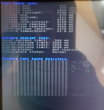
The Battery seems ok from a quick launch of RCM Hekate, but I will check that more later on.

Block Image

My Connector-Pin Diode Readings:

Block Image
crwdns2934089:0crwdne2934089:0 crwdns2934093:0crwdne2934093:0

crwdns2934109:0crwdne2934109:0

crwdns2889612:0crwdne2889612:0 0
crwdns2934285:0crwdne2934285:0

crwdns2933315:02crwdne2933315:0

crwdns2934057:0crwdne2934057:0

Hi!

Okay, this is definitely burned in the screen.

Also a part of the backlight is broken.

Replacing the LCD is the only option to get this fixed! It's not very difficult to do so too!

Here is the guide you need: Nintendo Switch Screen Replacement - iFixit Repair Guide

If you have any more questions, please let us know!

crwdns2934105:0crwdne2934105:0

crwdns2889612:0crwdne2889612:0 2

crwdns2944067:06crwdne2944067:0:

Hey thanks a lot for the response! I swapped the LCD with a known working one from another console just now and surprisingly the Working LCD showed similar issues on the broken console. When I then added the 'Broken' LCD to the working console was fine. So I now do not think it is an issue with the LCD, I have added photos to my post to show this.

Would you have any other suggestions on what I should check next?

I might start checking the backlight circuits tomorrow.

Thanks again

crwdns2934271:0crwdnd2934271:0crwdne2934271:0

@choggy hmm, weird. It is something on the motherboard and this moment and it does sound like the GPU. Especially the “burned in” image. You can check the backlight circuits. Could also be the LCD connector. Does this one look fine and are all the pins intact? Atm it does sound like the GPU unfortunately…

crwdns2934271:0crwdnd2934271:0crwdne2934271:0

@dan0 could be a faulty max series buck boost controller for the backlight vcc

I'd take diode mode readings of the LCD connector and compare them to a known working unit. Then I'd follow an out-of-spec traceback on the boardview schematics, which are out there somewhere.

crwdns2934271:0crwdnd2934271:0crwdne2934271:0

Yes that is possible as well! Thanks for pointing that one out.

crwdns2934271:0crwdnd2934271:0crwdne2934271:0

@dan0 Thanks for the input, I have looked into the LCD connector and found a few differences in diode mode with a working console, visually it seems fine. Hopefully it isn't the GPU as I don't have a rework station yet. I have ran out of time to do more checks this weekend but I have updated my post with my findings, thanks again!

crwdns2934271:0crwdnd2934271:0crwdne2934271:0

crwdns2934273:01crwdne2934273:0

crwdns2934285:0crwdne2934285:0

could be a faulty Max Series buck boost controller for the backlight VCC

I'd take diode mode readings of the LCD connector and compare them to a known working unit. Then I'd follow an out-of-spec traceback on the boardview schematics, which are out there somewhere.

I also recommend confirming that the battery on the dimming unit is in good health.

See the following guides for board-level diagnosis:

https://www.retrosix.wiki/max77620-cpu-r...

https://www.retrosix.wiki/full-boot-from...

crwdns2934105:0crwdne2934105:0

crwdns2889612:0crwdne2889612:0 1

crwdns2944067:04crwdne2944067:0:

Hey, thanks a lot for the links and the advice. I I took some readings of the LCD connector and found 2 pins have OL when they should have 1.9v. I traced that back to an unknown cluster but I have not yet had the time to figure out much more. Would you have any ideas about what those voltages may mean? I will continue more next weekend then follow those guides you provided too thank you!

crwdns2934271:0crwdnd2934271:0crwdne2934271:0

@choggy was the LCD plugged and powered? the LCD might have an 'enable, okay, or ready' signal, so voltage readings may not be a reliable diagnostic method measurement in diode mode, pin to ground readings with the device powered off, never vary with logic states

EDIT : Yes I read update 2. Those two pins are the problem circuit that IC has an inductor and is a digitally controlled boost/buck DC-DC converter there, it is probably your issue

I can remove these parts from a donor board and find the values

if avabile check that area with thermals

crwdns2934271:0crwdnd2934271:0crwdne2934271:0

@adr_daniel Hey yea that would be great if you had time to check the values. I am trying do that myself currently but I am still learning to identify what component is what. Is the large silvery grey one the inductor? The resistance of that one slowly drops to stable for my readings, so I am thinking it is.

My multimeter is a cheap $50 tool so it does not seem to be able to read a stable inductance value on that one. My capacitance readings seem to be kind of unstable also.

Unfortunately I also do not have a thermal camera. But I will keep trying to identify the problem and exchange components.

Thank you again for the continued help!

EDIT: I have swapped the main IC in that circuit for a working one. but it still gave problems.

crwdns2934271:0crwdnd2934271:0crwdne2934271:0

@choggy, yes, the silver grey one is an inductor, and it should have low resistance

Check continuity to ground on both sides of the capacitors; only one side should show a value/beep in continuity, ohms, or diode mode. The inductors will show on both sides it is a common mistake people make is assuming they are caps and shorted. but all the little brownish ones near by are caps

crwdns2934271:0crwdnd2934271:0crwdne2934271:0

crwdns2934285:0crwdne2934285:0

crwdns2934229:0crwdne2934229:0

Connor crwdns2934231:0crwdne2934231:0
crwdns2936625:0crwdne2936625:0:

crwdns2936751:024crwdne2936751:0 1

crwdns2936753:07crwdne2936753:0 2

crwdns2936753:030crwdne2936753:0 75

crwdns2942667:0crwdne2942667:0 75