crwdns2933423:0crwdne2933423:0

Vizio e50u-d2 has no power

I've been trying to diagnose the issue with my Vizio e50u-d2 tv. I don't think it is getting any power and the standby light is not on. I'm considering buying a new power board but I wanted to discuss with someone if that is the right next step. this was the most helpful ifixit thread for my situation. I appreciate any help or insight anyone has. Here is what I have tried so far:

When I opened the tv I checked the resistance on the fuse and it showed infinite resistance so I assumed it blew out. I also checked the resistance across the green varistor right next to it and it was reading around 1.04 mega ohms and it visually didn't look cracked for burned, so I assumed it was good based on this link that was recommended in the ifixit thread I linked above.

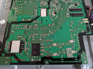
I removed the fuse and soldered in a new fuse of the same type (T5A250VP written on the fuse, ceramic axial slow blow fuse in the product description, and visually looks exactly like the one installed). The solder seemed to have good flow and the joints looked pretty clean (FS801 in the pic below). I know this isn't a perfect test, but I checked the resistance between the outside wall of each solder joint and the fuse itself. This showed <0.5 ohms so along with the visual inspection it gave me some confidence that the solder joints were good. I then checked the resistance across the fuse after soldering and it showed <0.5 ohm resistance (shouldve checked it before but I forgot, turned out ok though). For reference my multimeter only reads as low as 0.1 ohms I think.

Block Image
Block Image

So I then plugged in the tv to a surge protector. While plugging it in I wasn't looking at the tv, and I couldn't hear it very well, but what I think happened is the fuse blew as soon as I plugged it in (within 5 sec). I think I heard some faint electrical noise and maybe saw a flash in the corner of my eye, but it's difficult to know for sure. Now when I went back to the tv, there was no standby light. When I opened it up again the fuse showed infinite resistance so I assumed it blew again.

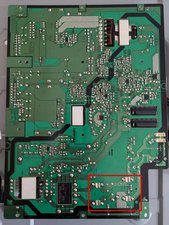
So obviously there is something else wrong with my tv. I'm still assuming it's the power board and I'm considering replacing the whole power board. I didn't notice anything visually that seemed wrong with it, like scorch marks for example, but I've added some pics of the board below if y'all notice anything that I don't.

Block Image
Block Image
Block Image
Block Image
Block Image
Block Image

I also tried testing the power cable. It also has very low resistance on both prongs. The cable visually looks brand new, no damage. When I plug just the cable into the surge protector I measure 115-120 V AC on from free end.

I appreciate any help or insight anyone has. If there's other things I should test, please let me know. Thank you in advance!

crwdns2934081:0crwdne2934081:0 crwdns2934083:0crwdne2934083:0 crwdns2934093:0crwdne2934093:0

crwdns2934109:0crwdne2934109:0

crwdns2889612:0crwdne2889612:0 1
crwdns2944067:02crwdne2944067:0

Hi @ss_pp

Might be expensive on fuses but wondering what happens if you replace the fuse and then before connecting the power to the TV, disconnect the power board from the rest of the boards etc in the TV i.e. isolate it, then reconnect the power.

Does the fuse blow?

If it does then yes it would be the power board, but if not it may be something else. No doubt if it holds there won't be a standby power light.

crwdns2934271:0crwdnd2934271:0crwdne2934271:0

@jayeff Thanks! I have a few extra fuses so I will try this on one of the upcoming weekends.

crwdns2934271:0crwdnd2934271:0crwdne2934271:0

crwdns2934285:0crwdne2934285:0

crwdns2933315:02crwdne2933315:0

crwdns2934051:0crwdne2934051:0

After reading everyone's replies/comments (thank you!), testing/diagnosing some more, reading more online refs, and getting some AI help lol, I think my issue is the bridge rectifier is faulty.

I'm going to document what I did in case anyone else has the same issue.

I ended up buying an entirely new power board so I'm able to compare it to my faulty power board. Here are the results from testing the rectifier on both boards. Put your multimeter in diode test mode if you've never done this, this was my first time. Also see the pic below, the rectifier and each terminal you'll be testing is labeled. I also included a circuit diagram with the same labeling since it helped me understand what was going on.

Block Image
Block Image

Bridge rectifier on new power board:

  • forward bias tests (online refs say it should be between 0.5-0.7 V):
    • Red probe on DC-, black probe on DC+: 0.500 V
    • Red probe on AC2, black probe on DC+: 0.466 V
    • Red probe on AC1, black probe on DC+: 0.465 V
    • Red probe on DC-, black probe on AC2: 0.464 V
    • Red probe on DC-, black probe on AC1: 0.464 V
  • reverse bias tests (online refs say it should read 0L or no reading):
    • Red probe on DC+, black probe on DC-: 0L
    • Red probe on DC+, black probe on AC2: 0L
    • Red probe on DC+, black probe on AC1: 0L
    • Red probe on AC2, black probe on DC-: 0L
    • Red probe on AC1, black probe on DC-: 0L

Bridge rectifier on faulty power board:

  • forward bias tests (online refs say it should be between 0.5-0.7 V):
    • Red probe on DC-, black probe on DC+: 0.501 V
    • Red probe on AC2, black probe on DC+: 0.469 V
    • Red probe on AC1, black probe on DC+: 0.470 V
    • Red probe on DC-, black probe on AC2: 0.820 V
    • Red probe on DC-, black probe on AC1: 0.821 V
  • reverse bias tests (online refs say it should read 0L or no reading):
    • Red probe on DC+, black probe on DC-: 0.388 V
    • Red probe on DC+, black probe on AC2: 0.820 V
    • Red probe on DC+, black probe on AC1: 0.819 V
    • Red probe on AC2, black probe on DC-: 0.820 V
    • Red probe on AC1, black probe on DC-: 0.821 V

crwdns2934105:0crwdne2934105:0

crwdns2889612:0crwdne2889612:0 1
crwdns2934285:0crwdne2934285:0
crwdns2934057:0crwdne2934057:0

@ss_pp following the DC in line it goes to the bridge rectifier but I am not sure what you got going on here (red rectangle). Anything that connects in there? It does not look like the lines are closed the way the board is right now. I could be wrong, so check with your multimeter and see if you have continuity on that line the way the board is right now. If you do not have continuity, replace the fuse and plug your board in. If the fuse still fails, you know that the short is between the rectifier and the fuse. It'll be easier isolated.

Block Image

crwdns2934105:0crwdne2934105:0

crwdns2889612:0crwdne2889612:0 1

crwdns2947414:01crwdne2947414:0:

@oldturkey03 Thanks for the response! I'm a little unclear on what you want me to check. Can you explain it a little more plainly? My experience is limited.

This is what I checked. The fuse is currently blown so of course no continuity across it. I did replace the fuse a 2nd time and it blew immediately, and then I checked the following. I have continuity from the fuse (the lower node in your image, opposite of where the power comes in) all they way to the rectifier node (1 above the node labeled with "+"). I looked for shorts across any components that connect the 2 traces you have highlighted with the red box, and I didn't find any. All of those components measure around 1 mega ohm.

crwdns2934271:0crwdnd2934271:0crwdne2934271:0

crwdns2934285:0crwdne2934285:0

crwdns2934229:0crwdne2934229:0

s_p crwdns2934231:0crwdne2934231:0
crwdns2936625:0crwdne2936625:0:

crwdns2936751:024crwdne2936751:0 0

crwdns2936753:07crwdne2936753:0 0

crwdns2936753:030crwdne2936753:0 10

crwdns2942667:0crwdne2942667:0 65