Water Dispenser - Only Works when Compressor Off
My water dispenser only works when compressor off. I replaced water solenoid and issue persists. Thinking maybe control board.
I've done extensive testing and I have determined that water only dispenses when compressor off. I was having an issue earlier and I thought it was due to water freezing. Now the problem is solid so easy to recreate.
Water won't dispense. I unplug fridge wait 10 minutes, plug in, turn on, try water and it works. Shortly thereafter compressor kicks in and water stops. When fridge reaches desired temp compressor will turn off, (I've sat and waited). Once compressor off water flows, no issue. If I open fridge door and force compressor on, water stops. Closed door, still no water. Wait for compressor to turn off, water flows.
This has me thinking that door switch is okay, and no broken wires. Remember I can unplug fridge, wait 10 minutes plug in and water flows. As soon as I hear compressor water stops.
Thoughts on what this might be or another test I should run to see if this is another component. Fridge and freezer run well, temps are controlled.
Any help would be appreciated.
crwdns2934109:0crwdne2934109:0

crwdns2947414:01crwdne2947414:0
Thanks. I think we have quickly approached my limit in terms of testing. Pulling connectors off board and then turning on fridge seems risky for a weekend warrior. If there is feedback voltage it seems strange that both the old and new water solenoids would display the same characteristics.
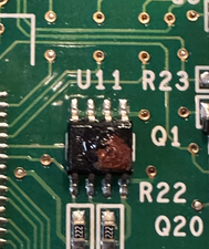
I'll take a look at control board and see if I can even identify these measure points.
Seems to me that if anyone of these is bad it again points back to control board
crwdns2934271:0crwdnd2934271:0 Ken W crwdne2934271:0