crwdns2933423:0crwdne2933423:0

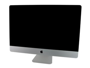
Model A1312 / Mid 2010 / 3.2 GHz Core i3 or 2.8 & 3.6 GHz Core i5 or 2.93 GHz Core i7, ID iMac11,3

crwdns2934591:0382crwdne2934591:0 crwdns2934593:0crwdne2934593:0

iMac A1312 27" no backlight after CPU Upgrade

I have a 27" mid-2010 iMac A1312 with an i3 CPU and I have upgraded the CPU to an i7-870. The problem I have is that after reassembling everything, the backlight is not working. The imac turns on and I can see image on the screen if I use a flashlight, and if I connect an external monitor I can see that it is working and I can use it normally.

All 4 diagnostic LED's that are at the bottom of the logic board are on.

I have replaced LED driver board and the issue persists.

I have replaced the LVDS cable and still have the same issue.

I know that the display LED's are good because I've tested them with an LED tester and they turn on, I even tried it with the computer on and I could see the desktop.

I've read on the forum that the GPU might be the issue because it doesn't send the signal for the backlight to be turned on. Can this be the issue or might be the logic board? (logic board model is 820-2901-A)

Thank you for your help.

crwdns2934081:0crwdne2934081:0 crwdns2934083:0crwdne2934083:0 crwdns2934093:0crwdne2934093:0

crwdns2934109:0crwdne2934109:0

crwdns2889612:0crwdne2889612:0 0
crwdns2934285:0crwdne2934285:0

crwdns2933315:02crwdne2933315:0

crwdns2934051:0crwdne2934051:0

A comment about the backlight enable signal: the logic board has test points for probing this signal. It may be difficult with the display installed, but you could use a multimeter to measure the voltage between ground and the backlight enable signal, which would give you a good indication of whether or not the backlight hardware is faulty, or if the computer just isn't enabling the backlight. You should be able to find more details about these test points in the factory service manual for the machine, which can be found with a quick google search.

crwdns2934105:0crwdne2934105:0

crwdns2889612:0crwdne2889612:0 1

crwdns2944067:04crwdne2944067:0:

Yes, it's Pin 13 Backlight Enable (signal from logic board to Backlight Controller board, to enable backlight), however, IDK if this should have constant voltage or just when that logic board powers on, and what voltage am I looking for 3.3V, 5V or 12V?

crwdns2934271:0crwdnd2934271:0crwdne2934271:0

Not 100% sure, but I'd guess 3.3V or less and consistently on. Anything other than 0V would indicate some kind of activity on the line. There's a separate pin (#6) on the debug connector which contains a pulsed signal (probably a PWM) to set the display brightness. You'd need an oscilloscope to really see what's going on there, but start with a multimeter on pin 13.

crwdns2934271:0crwdnd2934271:0crwdne2934271:0

I did check the voltage on pin 13 and there was none. I tested the backlight enable circuit and discovered a trace was broken. I fixed it and now I have backlight. Thank you all.

crwdns2934271:0crwdnd2934271:0crwdne2934271:0

Glad it's working!

crwdns2934271:0crwdnd2934271:0crwdne2934271:0

crwdns2934285:0crwdne2934285:0
crwdns2934057:0crwdne2934057:0

Let’s back up here a bit.. the system was fully working before you started correct? You also state you tested the LED’s how did you do that and what points where you measuring from.

The LVDS cable is not the the cable to be concerned with as the backlight LEDs are driven from the cable which comes from the LED driver board. Did you verify if voltage was present on the lines referencing the schematics and board view drawings?

This series had issues with the LED strip within the display there is two wires which are soldered to the legs coming from the LED strip board which often becomes de-soldered as the Tin solder weakens over time from the heat.

crwdns2934105:0crwdne2934105:0

crwdns2889612:0crwdne2889612:0 1

crwdns2944067:03crwdne2944067:0:

The system was functional befor the CPU upgrade. I tested the LED's at the connector that connects to the LED driver board and all work. Should I re-solder the connections at the bottom of the display? It's strange since the display was working before.

Should I check for voltages on the logic board? I checked the LED driver board and it puts out 12v on the correct pins when the system is on.

crwdns2934271:0crwdnd2934271:0crwdne2934271:0

Then you need to trace the lines back to the display either checking voltages or continuity. The metal shield on the back side of the panel assembly covers the wires leading to the LED strip along the bottom edge. You’ll find two wires entering from the back. Gently pull and press on each (doesn’t take much the wires shouldn’t give) if they do the wires have become loose at the LED board.

crwdns2934271:0crwdnd2934271:0crwdne2934271:0

the wires seemed secured not loose. to further investigate, I will have to disassemble the metal frame around the display but I have not done that ever and I am a little reluctant not to damage the screen.

crwdns2934271:0crwdnd2934271:0crwdne2934271:0

crwdns2934285:0crwdne2934285:0

crwdns2934229:0crwdne2934229:0

Andy crwdns2934231:0crwdne2934231:0
crwdns2936625:0crwdne2936625:0:

crwdns2936751:024crwdne2936751:0 0

crwdns2936753:07crwdne2936753:0 1

crwdns2936753:030crwdne2936753:0 4

crwdns2942667:0crwdne2942667:0 76