crwdns2933423:0crwdne2933423:0

The fourth generation Z4 workstation. Made by HP and first released in 2017.

crwdns2934591:02crwdne2934591:0 crwdns2934593:0crwdne2934593:0

Gets power and fan spin. No POST

I recently acquired one of these workstations that I'm trying to get up and running. Here are the symptoms in case anyone has ideas, but I currently have it narrowed down to either the Power Supply, or the board.

  1. Turns on when you connect power. You do not need to press the power button. It just turns on.
  2. CPU, GPU, and PSU fans all spin. PSU will start to spin aggressively if left on for a while. (I don't remember if the memory fans spin; I took that assembly out so I could see).
  3. No video output. Can't try onboard graphics because it has a Xeon CPU. So no iGPU.
  4. No beep codes, blink codes, or other errors.

I would specifically like to know if the PSU is at fault (it's my current theory). Problem being. it's a proprietary power supply.

So. How do I test it? I am probably going to take the housing off and just look. But NOT TOUCH anything because I don't have a death wish. But I'm invested. And this is taking up residence in my brain.

PSU in Question. Specs/model number and weirdo connectors.

Block Image

Block Image

I'll probably cave and buy a new one, but I would rather be sure before I invest $$.

Stuff I have already tried. In case someone has other ideas that aren't Power Supply.

  • Parsing down to minimum config (Only CPU, one stick of RAM)
  • BIOS recovery
  • Installing a known good GPU
  • Remounting the CPU
  • Swapping RAM sticks around (It has 8 slots. 3 were populated. I verified they were in the correct layout and tried various sticks in the Number 1 slot.

UPDATE 04.20.2024 - Somehow this thread keeps finding people and I have still not fixed this or found a definitive answer to my question, but hopefully these voltages will help someone, or at least contribute to this discussion. I should add, I do not believe these voltages are correct.

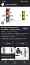
Measured voltages on my connector when both connectors are attached to the board and power on is attempted.

Block Image

Colors are constent with typical markings

  • Orange = 3.3V
  • Red = 5V
  • Yellow = 12V
  • Black = Ground or Voltage measured
  • Purple = 1V (I am not convinced this is normal, but nevertheless have nothing specific to compare to).

Even though my device powers on almost immediately after the PSU is connected to power, I can power off. Voltages with the power off.

Block Image

Anything not marked has no voltage and all previously 12V lines have very nominal voltage (~.08V).

I am again starting to think the PSU is to blame. I have checked the board pretty thoroughly previously for shorts, but since it is a rather large board, this is somewhat difficult.

crwdns2934089:0crwdne2934089:0 crwdns2934093:0crwdne2934093:0

crwdns2934109:0crwdne2934109:0

crwdns2889612:0crwdne2889612:0 2
crwdns2944067:02crwdne2944067:0

Thank you very much. It is a big help. Could you please measure the C12 as well with switched off and on state?

Some observations:

1. Good news: Pin 8 definitely is the PWR_STBY 5V.

2. PSU sticker is not mentioning 3.3V rail but you measure it on C18. I am a bit clueless on this. Could you measure C18 without connecting to the MB? Do you get 3.3V on P18 when the PSU is in standby?

3. P10 is the PWR_ON probably

4. P12 maybe the PWR_OK I am not sure.

Made some comment at the bottom as well.

Waiting for your answers!

crwdns2934271:0crwdnd2934271:0crwdne2934271:0

I believe the purple wire is the input to the PSU that turns it on - short green and purple. That is what the power switch does as seen here.

https://www.instructables.com/How-to-Tur...

As such, 1V is a floating input.

crwdns2934271:0crwdnd2934271:0crwdne2934271:0

crwdns2934285:0crwdne2934285:0

crwdns2933315:05crwdne2933315:0

crwdns2934057:0crwdne2934057:0

Hi Alisha @flannelist,

Get one of those PCI slot motherboard diagnostic Post Code readers which will tell you at what point the power on process dies.

Note that the codes may stop just before the problem. Makes sense right? If a component in the sequence is not working no code willi display so the one before will.

The better ones also show the 5 and 12 volt levels, etc.

crwdns2934105:0crwdne2934105:0

crwdns2889612:0crwdne2889612:0 2

crwdns2944067:06crwdne2944067:0:

I should get one of these anyway. I so rarely troubleshoot desktops. But it would probably be worth it for the times I need it.

crwdns2934271:0crwdnd2934271:0crwdne2934271:0

Bill @ruggb is the man but more info on Post Code Readers

They can save a lot of time for hardware problems. Here's more detail, from manual, on the voltage reading functions:

"Power on the system . . . .The 6 LEDs on the card represent

PCIRST, +3V3SB, +3.3V, +5V, +12V, and โ€“12v.

a) PCIRST LED - When the system is first power up, this LED will turn on momentary and then off, it will remain off after the initial boot up. It will stay on if one of the following is true

1) The reset switch is defective, try disconnect the reset switch.

2) Power supply is defective or

3) The motherboard is defective or grounded to the case.

b) +3V3SB LED โ€“ This is the standby power indicator. It will be lit only if the power plug is plugged into the motherboard, the on/ff switch on the power supply turn on, and the +3v standby power is present.

c) For 3.3V LED & the rest โ€“ This light should stay on after the system is turned on. It means the indicated voltage is present."

crwdns2934271:0crwdnd2934271:0crwdne2934271:0

@flannelist I have one of these and haven't used it in MANY years. Also, there is a possibility that the PSU is bad. You can check the voltages by starting the PSU with a jumper from green wire to black wire, check YouTube for directions, then measure the voltages on the pins. You can also use a PSU test box, but if you are not regularly fixing computers it is not necessary. Note that this will not test the PSU for its ability to handle the loads, it is only testing that the cause of the low resistance is not in the PSU itself.

crwdns2934271:0crwdnd2934271:0crwdne2934271:0

@ruggb Only problem is because it's a proprietary HP PSU I'm not sure what pin is supposed to be what. I can't find Pin Outs for it anywhere. It's an 18 pin for the main power connector and 12 pin for what would be the equivalent of the EPS.

Although. I plugged the PSU into the wall without it plugged into the board, and it still turned on (light, fan and all) the second I plugged in. Which makes me think this *is* actually the power supply. I ended up getting super busy and not working on this at all today.

This would be so much easier if there weren't weird manufacturer specific power supplies. And I could just plug a spare ATX PSU in.

I did measure 12V, 5V and 3.3V on various pins at the connenctor when it was connected. So the appropriate voltage is making it to the board.

crwdns2934271:0crwdnd2934271:0crwdne2934271:0

HPs get weird. If it starts without being plugged in, does it get warm also?

It is a switcher and the only thing it is running would be its fan. It should not get warm with that load.

From the manual.

To test the power supply:

1. Remove the power supply from the computer.

2. Connect the power cord to the wall outlet.

3. Connect power cord to the power supply.

4. If the power supply fans turn on and the built-in self-test (BIST) light illuminates, the power supply is

good and the power supply does not need to be replaced.

Get manual here

https://www.itcreations.com/user-manuals...

crwdns2934271:0crwdnd2934271:0crwdne2934271:0

crwdns2934273:01crwdne2934273:0

crwdns2934285:0crwdne2934285:0

Two clues:

  1. it starts without pressing the power button
  2. The PSU fans run fast after a while.
  3. The fans run

That would indicate to me there is a short or a very excessive load on the 5V line.

Fans run on 12V. So, the 12V line is good.

The start circuit is controlled by a transistor on the 5V line. The PSU fans are running fast because the PSU is heating up trying to supply the load.

TRY:

measuring the resistance on the 5V circuits at the MB connector with the PSU connectors removed.

Using I = E/R, verify R is high enough so I is less than 1/2 PSU rating.

If R is too low, you must find the cause. Start by pulling the CPU and remeasuring. Continue removing parts till you find it. If you don't find anything that way, then the issue is likely a soldered in device on the MB or the power conditioning circuits for the CPU. That may mean a MB replacement unless you can locate and replace the bad part. Start by checking capacitors. I would use a low reading Ohmmeter. I found a shorted cap on an old IBM 5150 the other day that way.

If this works, give me 5!!!!!!

crwdns2934105:0crwdne2934105:0

crwdns2889612:0crwdne2889612:0 1

crwdns2944067:011crwdne2944067:0:

This is brilliant. And would make perfect sense. I was already thinking a short because it turns on right when power is connected. I literally checked the board power switch for resistance/continuity. But I wasn't convinced I was testing the right pins due to the way the switch is mounted, and never revisited it for some reason. I'm just so used to cell phones and laptops, and my brain wasn't making the translation.

This is just an iPhone VDD main short, but on a desktop computer. You exploded my brain.

I figured the PSU was blasting the fans because it was getting hot due to its own fault. But if there's a short... It's going full bore, dumping current into ground. I don't know why I didn't put two and two together.

I'm almost positive this is the board, but you're right, it's worth pulling everything and seeing if it still does it. And if it does I can find a board short. Hopefully, it's nothing god-awful and itโ€™s just a bad cap.. I'm gonna drive my girlfriend nuts diode moding this thing at 11:30 at night.

crwdns2934271:0crwdnd2934271:0crwdne2934271:0

@flannelist heyyy, did you manage to fix the board and/or find the issue? I have a hp z4 g4 doing the same thing ๐Ÿ˜ฌ would be nice if it isn't the cpu ๐Ÿ˜… did yours beep and flash no cpu when you removed it?

crwdns2934271:0crwdnd2934271:0crwdne2934271:0

@bazzaf I did not. This thing has become somewhat of a pet project (pretty much everything I fix these days outside work is a pet project). I got it in an offload of some machines from my job that we were just going to recycle so left the SSD at work for them to wipe and dispose and took the machine home. It just sits on my shelf until I can sort it and repurpose. Because this thing was too much of a beast to huck it.

I actually suspect really strongly in my case it's the PSU. I haven't tried uninstalling CPU for some reason, even though that was suggested.

I think I tried leaving RAM out, but not CPU. I can understand not wanting to replace that though. And I certainly don't have a spare CPU that will go in an LGA2066 socket to test. I suspect most people don't either.

crwdns2934271:0crwdnd2934271:0crwdne2934271:0

@bazzaf WAIT do you have a multimeter? If so, we can try and cross compare PSU or any values really since nobody seems to have a pin out out posted anywhere. I was coincidentally looking at that on my shelf today wanting to poke at it so let me know.

crwdns2934271:0crwdnd2934271:0crwdne2934271:0

@flannelist %100, I have a few multimeters, yes. ๐Ÿ˜Š im quite the hobbyist, one of which hobbys include some weird form of electrical engineering, mainly the form that doesn't like to throw away expensive things without trying far too hard, and spending far to much time on to try and fix it! When that fails, it's components get harvested and used in other diy electronic projects. ๐Ÿ˜† I will open my psu up this week sometime, try to probe it as best I can and get back to you ๐Ÿ‘

crwdns2934271:0crwdnd2934271:0crwdne2934271:0

crwdns2934275:06crwdne2934275:0

crwdns2934285:0crwdne2934285:0

@flannelist hey! I've got my psu open. Once the side panel was removed and one ziptie on the main output harness was cut, it folded open rather nicely. I've been probing it a little to cross reference between a pinout of the connectors I found on the Great interwebs. So far most of it is the same. I will try and add a screenshot of it for you.

Block Image

crwdns2934105:0crwdne2934105:0

crwdns2889612:0crwdne2889612:0 1

crwdns2944067:03crwdne2944067:0:

Somehow I missed this pin out in all of my searching. Thanks!

So couple follow up observations. When I plug in the PSU, but not connect it to the board, it spools up, but I only get power on the small connector (12V). Not sure if that's normal. It might just be.

I don't believe I checked pin voltages before I opened it. At least not without it being connected to the board since I wasn't even expecting it to power up with no board attached. I'll have to connect it today and see what I can find.

crwdns2934271:0crwdnd2934271:0crwdne2934271:0

@flannelist I have not gone over the whole pinout I posted, but seems to be right compared to any other I've come across!

Interesting how yours acts when disconnected from the motherboard. Mine is the opposite, dissconnected from the motherboard, mains power connected and nothing happens, apart from the green light on the back illuminates. It might be that we have two different problems! I will find some time to do some more probing, and confirm some more of the pinout earlier posted.

crwdns2934271:0crwdnd2934271:0crwdne2934271:0

@bazzaf Based on what I was finding on the PCB of the PSU, it may actually be that this PSU is 12V only. Most other PSUs I have seen are marked indicating other voltage rails. This one only has 12V marked anywhere I looked.

I actually thought initially that the PSU was the issue because it powers on when connected to mains, but the service manual actually calls out to remove the PSU from the computer and connect to power. "If the power supply fans turn on and the built-in self-test (BIST) light illuminates, the power supply is good and the power supply does not need to be replaced."

Now I feel like yours might be a power supply issue. But I am not sure mine is. I still think mine is a board short. Especially since it powers on as soon as I connect power (the whole computer, not just the PSU).

crwdns2934271:0crwdnd2934271:0crwdne2934271:0

crwdns2934285:0crwdne2934285:0

Hi, I have a G4 Z4 Xeon MB and I amgoing to figure out wether it is working or not. I do not have the Z4 PSU therefore I have to decode the 18 pin and the 12 pin PW connector pinouts to be able to connect an ATX PSU. I have some experience in HW troubleshooting feel free to ask.

What measured so far. Name the 18 pin PW MB connector's pins as the previous post's Z400 PW connector. Pin 1 is left side pin next to the memory slots, Pin 10 is the oposite pin to Pin 1.

The possible GND points are:

on the right side: P17, P16, P15

on the left side: P4, P5, P8

On the 12 pin PW connector (CPU MEM PWR):

Pin1 top of the pin next to memory slot, Pin 7 is the opposite one to Pin 1, next to the MB PCB.

The possible GND points are:

on the right side: P7, P9, P10, P11, P12

I am asking Alisha to measure with the multimeter the other pin's voltages referencing the ground pins as follows in order to determine wether the PSU is OK or not. It is easy to measure. Do not forget to mirror the pin numbering from the PSU mother connector.

  1. In normal cases when the PSU is powered but not connected to the MB than the PS_STBY, PS_GOOD and PS_ON pins should be present as 5V. There should not be 12V on any other pin. Please try to find which pins have 5V. If there are two or three of them than it is OK. Please connect the 18 pin PW connector to the MB. Put the MM positive probe into the back of the connector of the PSU to one of the pin showing 5V the other probe to Ground and press the power button. If the 5V drops to near zero than that pin is the PS_ON pin and the other one having 5V is the PS_OK or PS_STBY. I would appreciate if you could give me these two-three pin's numbers.
  2. Please disconnect the PSU from the MB. You have the PS_ON pin and the GNDs. I suggest to use an 1kohm resistor and some wire to make a connection between the PS_ON and GND. In this way you can start the PSU without the MB. Measure the voltage on the other pins. There should be 12V and 5V present on multiple pins. If the PSU is in disassembled state yet than I ask a favor: please check the cables of the 5V from the connector to the PCB of the PSU: You will see one of the 5V cable is not going to big puffer capacitors. That 5V cable is the PS_GOOD signal cable. Please share the Pin number.
  3. Maybe some pin has no voltage "floating pins" at all. It is not a problem, document these pins please. Later on the voltage should be tested again with connected MB on these pins.
  4. If the 12V, 5V are present in "standalone" mode that remove the jumpstart wire, connect the PSU to MB, push the power button and measure the voltages of the PSU connector's back. It should be 12V, 5V on the same pins as you measured standalone and maybe 5V on some of the "floating" pins. Please document these voltages-pins as well if any.
  5. Please do the same measurements on the 12 pin PW connector as well and share the measurement results.
  6. That is it for the first round to figure out the state of the PSU. Any comment is welcome, let use-test this beauty MB. I am more than happy to help you to diagnose your board because I have to do the same with mine!

crwdns2934105:0crwdne2934105:0

crwdns2889612:0crwdne2889612:0 1

crwdns2944067:09crwdne2944067:0:

One more thing: when you starts the PSU with the 1kohm resistor than it should be enough just a short connection and release. Check the multimeter. If you connect the PS_ON to GND and the 12V appears than release the jumpstar resistor. Two things could happened: 1. 12V dissapears than the connection should be keep during the power on time. 2. 12V stays. In this case the next short will switch off the PSU. It depends on which standard HP is implemented.

crwdns2934271:0crwdnd2934271:0crwdne2934271:0

@mimihaly This was extremely helpful actually. This is one of those issues I have been overthinking. My grounds match with what you found. On the board side, I will have to take the board out again and measure voltage. Although it does make sense that there is still some level of power on pin. Despite the fact that the PSU does get some kind of power when disconnected from the board (12V rails on the 12 pin are present)

I am not getting anything on any of the pins on the 18 pin however.

Can you get me resistance mode or diode mode readings for the rest of the 18 pin connector connector on the board side? Just to compare?

crwdns2934271:0crwdnd2934271:0crwdne2934271:0

OK, for further reference I suggest to name the 18 pin connector to C18, the 12 pin connector to C12.

My diode mode measurements:

on C18:

MM ground probe on GND, positive probe on test pins:

P1: 1.255v

P2: capacitor charging

P3: capacitor charging

P6: capacitor charging

P7:capacitor charging

P9: slow charging

P10: 0L, reversed probes: 0L, possible output?

P11:capacitor charging

P12: 0L, reversed probes 0.751V possible output?

P13: capacitor charging

P14: capacitor charging

P18: capacitor charging

Pins not mentioned are GNDs.

on C12:

MM ground probe on GND, positive probe on test pins:

P1: capacitor charging

P2: capacitor charging

P3: capacitor charging

P4: capacitor charging

P5: capacitor charging

P6: capacitor charging

P8: capacitor charging

Capacitor charging means the measurement starts with 0.5V and quickly - 5-10s - rise to 2.9V and it changes to 0L. If you want to measure a given pin again discharge the pin first otherwise it will be 0L.

crwdns2934271:0crwdnd2934271:0crwdne2934271:0

Before the measurement I recommend to short these pins to GND with a wire to discharge the input capacitors for one or two seconds. If you measure 0L on a pin reverse the probes and measure. Reverse back the probes and measure again. (its a kind of discharge).

If you measure shorts - continuous beep - on these pins than you have a problem: that rail is shorted but do ot worry most of the case it is easy to repair. But first the PSU should be in working order.

crwdns2934271:0crwdnd2934271:0crwdne2934271:0

You measure no output voltage on any pin on C18 connected to Power and unconnected from MB?

You got 12V on C12 pins? If yes which ones? This is a bit strange because mem and cpu power should be present after the psu is switched on by the user but maybe I am wrong.

I suggest to deal with C18 only first. If there is no voltage on the pins when not connected to the MB than connect to the MB. Connect C12 as well.

Measure voltages on the C18 connector in the plugged state. Push the multimeter measure probes to the top of the connector, you should reach the connector's pin with the probes - you should see the top end of the metal pin in the connector-. In case of the ATX PSU it is possible to measure this way with plugged in connector.

Than push the power on button on the front panel and measure again the C18 connector.

Please reply back with the measurements.

Waiting for your results.

crwdns2934271:0crwdnd2934271:0crwdne2934271:0

crwdns2934275:04crwdne2934275:0

crwdns2934285:0crwdne2934285:0

Hi everyone. Sorry if I get involved in this discussion but it's a similar problem.

They gave me a motherboard/processor/ram that was supposed to be from this Z4 G4. Unfortunately I can't test it due to the usual 18pin power supply problem. I'm considering buying a 24 to 18 pin adapter, the only doubt I have is: the motherboard also has another 12 pin input, do I necessarily have to connect this too to make it work? Can someone detach this second PIN and tell me if it still works? In my opinion an adapter cable is also the solution to the problem of this thread, with little expense try a standard power supply and you don't have to waste hours and hours in testing.

crwdns2934105:0crwdne2934105:0

crwdns2889612:0crwdne2889612:0 0

crwdns2944067:05crwdne2944067:0:

I am not sure if the ATX converter cable is applicable for the Z4G4. According to the sticker on the PSU several 12V and one 5VSTB is provided on the C18, and several 12V rail on the C12. There is no 3.3V rail in the HP PSU. There is not exact pinout of the two PSU connectors therefore the ATX PSU connector conversion can not be determined yet. Please note you face one more problem. There is no pinout for the front I/O connector as well, therefore the switch on-off button pins should be determined by experience on the yellow male pin header. In order to start the PSU and have right signaling on the chipset this is a must I believe. I am in the same shoes as you. Still looking for somebody have a working system an be able to measure the C18, C12 by multimeter to document the pinout of these connectors.

crwdns2934271:0crwdnd2934271:0crwdne2934271:0

@mimihaly Agreed that is does not match the standard 18 + 12 pin that was previously posted.

@marcoguerra I have read in places that it is unwise to use adapters like this for this specific PSU for numerous reasons. It may be able to be done, but there would have to be some rewiring at a minimum to match the pinouts on this power supply and I would question that it would be worth it rather than buying an HP power supply.The risk for damage to the board is too great in my opinion

crwdns2934271:0crwdnd2934271:0crwdne2934271:0

Alisha, based on your measurements on C18 it seems the PSU provides all the main (5V, 12V) rails on that connector. PWR_ON switching is working as well.

Pin 12 needs to be investigated. It is definitely driven by the MB. The measured 1V is not normal I think. Measure it on the PSU's connector without connecting to the MB please.

The 3.3V pins (Pin1, Pin 10) should measured C18 disconnected from MB on the PSU side.

Pin 2 measurement is a promising one. On standby it is 3.3V, switched on it is GND. It indicated that the given rail is shorted to ground when the PSU is switched on. Let me check on my board which power rail belongs to P2. If you are lucky only a shorted mosfet is your problem.

crwdns2934271:0crwdnd2934271:0crwdne2934271:0

@mimihaly I checked any of the mosfets I could spot readily for shorts (and voltage) and checked coils for appropriate voltage on both sides and found everything as I would expect. Doesn't mean I didn't find th problem, but I would be very okay with that if I am nust missing something.

I have a new power supply coming tomorrow just to rule it out, but I would be very okay with a shorted mosfet. I'll keep you updated.

crwdns2934271:0crwdnd2934271:0crwdne2934271:0

Alisha, is it possible to PM you? If the existing PSU turns to be bad than I am interested to buy it if it is for sale.

Regarding the board: something pulling down the P2 from 3.3V to GND on switch on. I measured P2 as a power input on the MB.

I would check it in the following way: using a variable power supply I set the current limit to 3A and I powered P2 only starting from 0.5V and increasing slowly up until it reaches the 3A limit or 3.3V. (voltage injection) If you reach 3A before the 3.3V (very likely) than check the MB what is getting hot. Use infra camera or isopropyl alcohol to identify the component getting hot. Possibly a shorted capacitor but who knows.

crwdns2934271:0crwdnd2934271:0crwdne2934271:0

crwdns2934285:0crwdne2934285:0

crwdns2934229:0crwdne2934229:0

Alisha C crwdns2934231:0crwdne2934231:0
crwdns2936625:0crwdne2936625:0:

crwdns2936751:024crwdne2936751:0 1

crwdns2936753:07crwdne2936753:0 65

crwdns2936753:030crwdne2936753:0 255

crwdns2942667:0crwdne2942667:0 989