crwdns2933423:0crwdne2933423:0

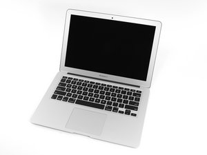
The March 2015 update of Apple's 13" MacBook Air features fifth generation Intel Core i5 and i7 processors, resulting in slightly increased performance and battery life.

crwdns2934591:0623crwdne2934591:0 crwdns2934593:0crwdne2934593:0

MacBook Air (early 2015): fix broken LCD backlight power

My sister spilled apple juice over her Early 2015 Macbook Air, and failed to switch it off immediately…

I managed to disassemble and clean it by following these excellent instructions so it at least boots again, but the backlight is broken. When pointing a flashlight to the display, it looks as if the LCD itself is not damaged afaict.

Searching the internet I found hints that it might be possible to fix this issue by replacing a fuse o a FET or a driver IC. Is this correct? Any hint where these components are located, and what are their specs? Or would it be better to replace the entire logic board?

Thanks in advance, Albrecht.

Edit: some (bad, created using a mobile) photos of the main board:

  • the cleaned mainboard after re-installing. I noticed corrosion in two places, indicated by the red circles:

Block Image

  • corrosion in the right location, close to the AirPort, before cleaning:

Block Image

  • same place, after cleaning:

Block Image

  • in the left location, close to the display connector, after cleaning (sorry, I don't have a photo with the corrosion, i.e. before cleaning):

Block Image

Apart from the broken panel backlight, the systems seems to be fully operational. I could log in, connect an external DP monitor, and test the following:

  • OK are: keyboard (checked every key), keyboard backlight, trackpad, both USB ports, external monitor out (DP), Wifi, Bluetooth, internal speakers, headphone, microphone, camera, SD card reader.
  • The battery is detected and charging (I guess I have to reset the SMC and re-calibrate it, though).
crwdns2934089:0crwdne2934089:0 crwdns2934093:0crwdne2934093:0

crwdns2934109:0crwdne2934109:0

crwdns2889612:0crwdne2889612:0 1
crwdns2944067:04crwdne2944067:0

@albrechtd that depends on your capabilities and tools as well as what may have failed. Besided checking that your backlight is not working, what else have you checked? Post some good pictures of your logic board with your question. That way we can see what you see and possibly offer some solutions. You do recognize that soldering very small components requires some pretty good skills and tools. Adding images to an existing question. Check the LVDS connector since it loves to corroded on the contacts

crwdns2934271:0crwdnd2934271:0crwdne2934271:0

Hi @oldturkey03, first, thanks a lot for your reply!

Well, I know that my skills are actually limited, although I'm an electrical engineer with some experience in hardware design and prototyping, have access to semi-professional SMT soldering equipment and know how to use it (and a sip of Scotch will calm down my trembling fingers…). IOW, I think I might be able to replace a larger component with few terminals, but of course no TSSOP.

I added a few (bad) photos and a summary of my tests to the original question as you suggested.

Thanks, Albrecht.

crwdns2934271:0crwdnd2934271:0crwdne2934271:0

@albrechtd I am certain but do have to ask. You did clean the bottom of this board too, correct? Email me for further details that will go beyond what I can do on here. My contact address is in my profile

crwdns2934271:0crwdnd2934271:0crwdne2934271:0

Hi @oldturkey03, thanks again! Cool, the schematics, placement & your instructions will definitely be *extremely* helpful! I'll have to leave for a business trip for the rest of the week this afternoon, so I'll performy your checks this weekend and get back to you.

And, yes, I cleaned the bottom of the pcb, too… ;-)

Thanks, Albrecht.

crwdns2934271:0crwdnd2934271:0crwdne2934271:0

crwdns2934285:0crwdne2934285:0

crwdns2933313:01crwdne2933313:0

crwdns2934057:0crwdne2934057:0

@albrechtd Your board is a 820-00165 and right away of interes is image number 4. All of those parts are part of the LCD backlight driver circuitry. I allowed myself to modify your image with the reference designation

Block Image

Here it goes:

Reference designator F7700 is a 3Amp 32 V fuse in a 0603 package

Reference designator C8317 is a 1000pF 50V 5% capacitor in a 0603 package

Reference designator C7799 is a 10UF 50V 10% capacitor in a 1210 poackage

Reference designator C7797 is a 10UF 50V 10% capacitor in a 1210 poackage

Reference designator C7796 is a 10UF 50V 10% capacitor in a 0402 poackage

Reference designatorD7701 is a RB1060M-60G diode is a SOD 123 package

LCD Backlight BOOST

Reference designator L7701 is a 15UH 2.8A PIMB053T SM inductor

LCD Backlight BOOST

Reference designator Q7707 is a DMN5L06VK-7 Mosfet Array 2 N-Channel (Dual) 50V 280mA 250mW

Bklt Enable

Reference designator Q7706 is a FDC638APZ_SBMS001 Fairchild MOSFET -20V P-Channel 2.5V

LCD Backlight FET

Datasheets for Q7707 ansd Q7706 are avialble but let me know if you have trouble finding those.

For now I'd start to see if there is power to the LCD backlight by the fuse and work my way around the components. Check the boost circuit for sure.

This is what that circuit looks like

Block Image

As a quick check you can do something like this:

At backlight output, measured on pin 3 or 4 of the LCD connector,

  • 0v means short to ground, blown fuse, or no LCD conected. Check that you see an image on the LCD, check backlight fuse, check board via from FET after fuse to boost coil.
  • 8v means no short to ground, good fuse, but no boosting. Check BKL_EN is 2.7 to 3v at voltage divider going to enable pin of WLED driver, check BKL_PWM signal exists.
  • 27v or higher means all good, but your LCD cable or LCD backlight itself is blown.

crwdns2934105:0crwdne2934105:0

crwdns2889612:0crwdne2889612:0 2

crwdns2944067:03crwdne2944067:0:

Hi @oldturkey03, thanks again for your great help!

A first quick measurement shows that it's not the trivial case of a blown fuse, unfortunately…

I measure (using a DMM) 7.0V at the connector and at the output of the Schottky diode, and 7.3V at its input, i.e. there is (according to the data sheet) a current of a few milliamps only. I see the 7.3V on the whole chain up to the fuse (F7700) which IMHO means that both Q7706 and Q7707 are intact.

Unfortunately, I don't know the placement of the BKL_EN voltage divider (R7715/R7731) and the PWM input lowpass (R7704/C7704) so I cannot check the input signals to the LP8550 driver. Can you help me with that? It might also be worth to check the fault output, wouldn't it? More information might also be available from the fault registers of the driver, but I have no idea how to access that data from macOS.

Best, Albrecht.

crwdns2934271:0crwdnd2934271:0crwdne2934271:0

Sorry for my late reply, it took a little longer to get a scope during these pandemic days…

Unfortunately, it turns out that actually the LCD backlight driver (TI LP8550) seems to be broken. The input signals (in particular EN and PWM) look fine, but there is no boost switch (SW) output signal. As I'm not able to replace a BGA, I'm really lost here (i.e. the only option is actually to replace the logic board).

Anyway, a really big, big THANK YOU to @oldturkey03 for his excellent (!!) help – at least I could clearly identify the cause of the problem with your input!

crwdns2934271:0crwdnd2934271:0crwdne2934271:0

@albrechtd Reading through your post, my first thought was probably the bl driver. Looks like you nailed that down! There are quite a few mail in services that could easily replace this for you. Check around to see if there are any local to you. Ask them to also program the ramps for the new driver (if its not programmed, then when you change brightness, it will "slam" to the next level, not glide to is - not sure how to explain it well, but visually it is much cleaner when programmed correctly). Most likely you have a blown pad under there too, so it is not just a swap out the IC, but a little trace rebuilding as well!

crwdns2934271:0crwdnd2934271:0crwdne2934271:0

crwdns2934285:0crwdne2934285:0

crwdns2934229:0crwdne2934229:0

Albrecht crwdns2934231:0crwdne2934231:0
crwdns2936625:0crwdne2936625:0:

crwdns2936751:024crwdne2936751:0 7

crwdns2936753:07crwdne2936753:0 25

crwdns2936753:030crwdne2936753:0 116

crwdns2942667:0crwdne2942667:0 2,632