
Repair Beseler Dichro 45s circuit board.
I am trying to fix a 1990 Beseler Dichro 45s enlarger head. It is used to make color photographic enlargements. I believe the voltage at the light bulb socket is supposed to be a stabilized 82 volts. I am getting 90-91 volts at the socket. I am trying to figure out how to test the circuit board to determine what parts are going bad. This is solid state electronics.
crwdns2934109:0crwdne2934109:0
crwdns2889612:0crwdne2889612:0
1
crwdns2947414:01crwdne2947414:0
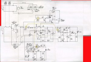
You are correct about the voltage. F. STABILIZED POWER SUPPLY The voltage for the colorhead's lamp and electronics are internally stabilized over an AC line voltage range of ±10% from the normal. I wonder what role the Vactrol Opto Couplers play in this. Seems to be one of the weak spots on those.
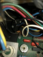
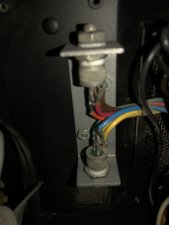
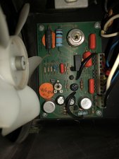
Can you post some good pictures of your power supply etc. with your Question? That way we can see what you see. Adding images to an existing question
crwdns2934271:0crwdnd2934271:0 oldturkey03 crwdne2934271:0