A number of my colleagues have dual U2413f monitors on their CAD workstations. One of them has developed the same fault as described in this thread, it shuts down when it heats up.
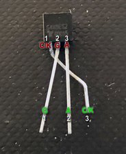
I saw the solution of changing the thyristors to ones with less sensitive gates. I couldn’t easily get suitable replacement parts locally, so I looked for a different solution.
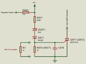
I drew out the schematic of the crowbar circuit which has a standard configuration. I decided that a simpler method of fixing the problem was to stiffen the Zener bias resistor to keep the thyristor gate voltage lower during normal operation.
The simplest method of achieving this is the put 1k in parallel with the existing 1k resistor resulting in halving the value.
The best part of this fix is that it can be done from the back of the PCB without unscrewing it and removing it from the metal frame.
For the benefit of others here is the process:
1. Using a plastic guitar pick type tool along the seam between the front bezel and the back of the case, press in the clips and release the bezel.
2. Place the monitor on its front and carefully lift off the back.
3. Lift the metal shield and carefully peel the ribbon cable adhesive pad off the LCD.
4. Press-in the clips and release the ribbon from the LCD.
5. Fold over the PCAs to access the back of the PCBs.
6. If necessary, the PSU PCA can be removed by squeezing the release clip on the inside of the PSU SIL connector on the signal PCA.
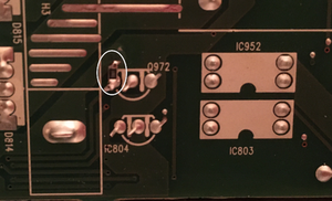
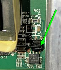
7. The thyristors in question, Q971 & Q972 have 1k between their gate and cathode.
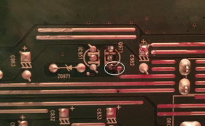
8. Reduce the Zener bias resistance to 500R.
9. Solder a 1k 0805 on the gate and scrape some resist off the ground plane and solder.
Since carrying out this modification the monitor has not had any further problems.
crwdns2934105:0crwdne2934105:0
crwdns2934113:0crwdne2934113:0
crwdns2915270:0crwdne2915270:0
crwdns2889612:0crwdne2889612:0
15


crwdns2944067:012crwdne2944067:0
Hi @dancarlocanlas ,
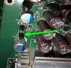
Have you checked the capacitors in the power supply section? Just in case they are bulging etc.
Just a thought.
crwdns2934271:0crwdnd2934271:0 jayeff crwdne2934271:0
yep. all capacitors and resistors seem to be fine -- no bulging, no burned parts, etc. I also noticed that if I provide ample air blowing at the back of the monitor, the issue doesn't persist. I do realize, this could work, but it might not be an ideal long-term solution.
crwdns2934271:0crwdnd2934271:0 Dan Carlo Canlas crwdne2934271:0
Hi @dancarlocanlas ,
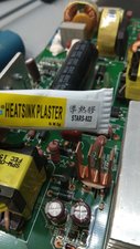
Can you replace / renew the thermal paste on the heatsink that you mentioned?
Cheers.
crwdns2934271:0crwdnd2934271:0 jayeff crwdne2934271:0
That's probably my next step, though I don't have an idea about thermal paste for electronic components. I only know about them for computer cpus. Do they have specific types for each application, or any thermal paste will do? Also, I'm looking at sticking a heatsink on top of the LD7904 chip (DIP), would that be advisable?
crwdns2934271:0crwdnd2934271:0 Dan Carlo Canlas crwdne2934271:0
Hi @dancarlocanlas ,
My untrained guess is that any new paste will be better than dried old paste.
As to putting on a heatsink. It may prolong the life of the component but if it is running hotter than it should due to whatever reason then it will fail eventually anyway, but definitely worth a try.
crwdns2934271:0crwdnd2934271:0 jayeff crwdne2934271:0
crwdns2934275:07crwdne2934275:0