crwdns2942213:0crwdne2942213:0
-
-
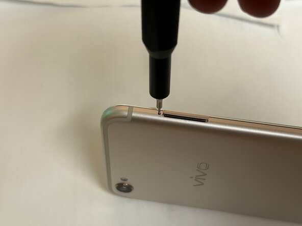
Remove the SIM card tray using a SIM card ejector tool.
-
-
-
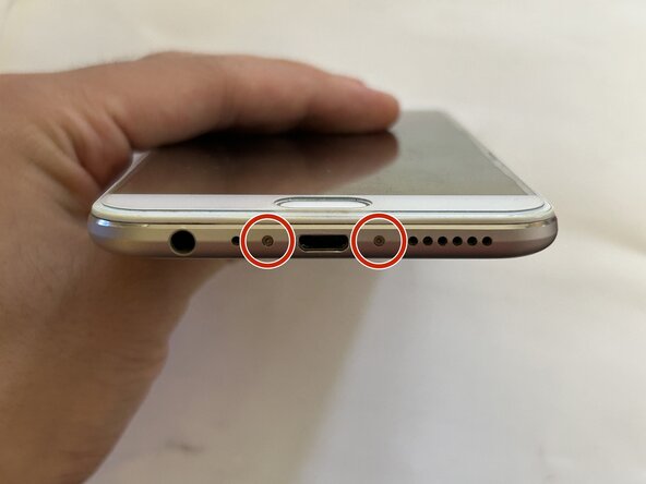
Unscrew the two T2 Torx screws on the bottom of the phone, surrounding the charging port.
-
-
-
Insert your opening pick or similar thin opening tool into the thin gap above the audio jack.
-
Force your opening pick as deep as it can. Push down on the pick to release the clips holding the housing onto the rest of the device.
-
-
-
Unscrew all visible screws on the top half of the device using a PH000 Phillips head screwdriver.
-
Peel the graphite pad off.
-
Unscrew the last Phillips head screw that was under the graphite pad.
-
-
-
Remove the bracket at the bottom of the motherboard.
-
Disconnect the other connectors shown.
-
Disconnect the antenna wires.
-
-
-
Follow the manufacturer's guide sticker to remove the battery.
-
-
-
Remove the bracket covering the double front-facing camera module, then disconnect and remove the module itself.
-
-
-
-
Remove the SIM tray bracket.
-
-
-
Carefully remove the yellow Kapton tape, then remove the bracket covering the display connector.
-
Disconnect and bend away the display cable.
-
-
-
Carefully remove the motherboard from the chassis.
-
-
-
Flip the motherboard over and remove the back-facing camera module.
-
-
-
Use tweezers to lift the cable for the vibration motor.
-
Use a spudger to finish removing the cable and motor.
-
-
-
Use the pointed end of a spudger to remove the earpiece speaker.
-
-
-
Remove the screws shown using a PH000 Phillips head screwdriver.
-
Screws marked with orange are hidden behind foam tape.
-
There is one screw with a warranty sticker on it. We've already voided our warranty earlier, so we unscrew it anyways.
-
-
-
Remove the cover of the daughter board.
-
-
-
Peel the ribbon cables running down the middle of the device, then peel the antenna cables running down the sides of the housing.
-
The antenna cables are routed through a small channel in the chassis that is covered with foam tape. The foam tape can be peeled back for easier access when routing the antennas.
-
-
-
Use a spudger to disconnect the antennas from both sides of the daughter board.
-
-
-
Using a spudger, disconnect the three connectors on the audio jack board:
-
Interpose cable
-
Daughter board display connector
-
Home button cable
-
Afterwards, remove the audio jack board.
-
-
-
Peel away the charging port.
-
-
-
Remove the two screws exposed by the removal of the audio jack.
-
There is another screw (marked with orange) that for this bracket that may be hidden underneath residue graphite tape. Ensure you have removed this screw or else you will damage the bracket when removing it.
-
-
-
There it is! The teardown is now complete. Opening the device was a bit tricky, but the insides are really easy to work with if you're careful.
-


