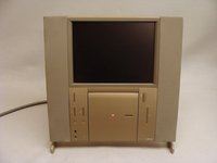
crwdns2942213:0crwdne2942213:0
-
-
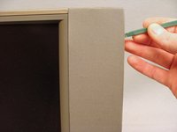
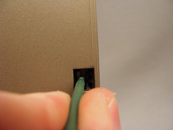
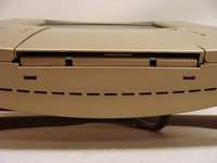
Use the release tabs to remove the rear cover
-
-
-
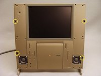
Remove any ComSlot II or PCI cards that may be installed and their risers.
-
-
-
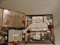
Unplug the logic board connections to the PRAM battery and fan.
-
Remove the PRAM battery from it's Velcro mounting.
-
Remove the four #0 Philips screws securing the hard drive and processor fan assembly.
-
Remove the hard drive and processor fan assembly.
-
-
-
Remove the two T6 Torx screws securing the A/V input board.
-
Remove the A/V Input board
-
-
-
Remove the white plastic shield
-
Remove the T6 torx screw securing the logic board to the frame.
-
-
-
-
Turn the TAM around with the front facing you.
-
Use a spudger to gently loosen the speaker covers from their press-fit snaps. Remove the speaker covers.
-
-
-
Remove the six T8 torx screws securing the front case to the rear case.
-
-
-
Gently pull the tabs toward the center to release the latches hold the front and back together. These tabs are fragile but release easily. Use caution.
-
Lean the top forward and lift up to pull the front case from it's bottom latches.
-
DO NOT TRY TO REMOVE THE FRONT CASE. It is still connected to the back case by several wires and cables.
-
-
-
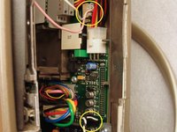
Disconnect the pink and white backlight inverter cable and the black and white right speaker cable from behind the floppy disk drive on the right side.
-
On the left side, disconnect the 50-pin SCSI ribbon cable, analog audio cable and power cable from the CD-ROM drive.
-
Disconnect the black and white left speaker cable.
-
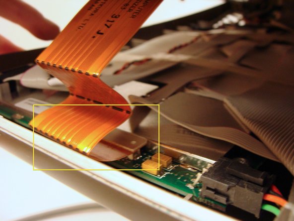
Disconnect the flat, orange display data cable.
-
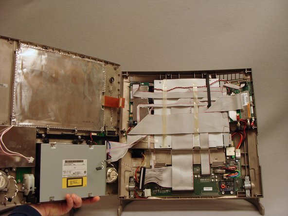
Open the top case to the left like a book. There will be one more 50-pin cable to disconnect from the front control panel board.
-
-
-
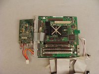
The easiest method to remove the logic board is to remove it with the tuner card and cabling.
-
Disconnect the five cables illustrated.
-
-
-
Remove the T10 torx screw and extract the stiff wire cable brace from the left side
-
-
-
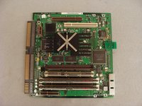
Carefully peel back the tape securing the cables to the white, plastic logic board cover. Pull the cables back to reveal the back side of the logic board.
-
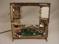
Remove the five T10 screws holding the logic and tuner boards to the back case.
-
-
-
Lift the logic board from the left edge then straight up to remove it from the rear case.
-
The logic board slides out of the cabling connector.
-


To reassemble your device, follow these instructions in reverse order.
crwdns2935221:0crwdne2935221:0
crwdns2935229:07crwdne2935229:0
crwdns2947412:04crwdne2947412:0
Hi,
One of the member of my Forum is looking for the Bose subwoofer including the power cable. Have you an idee on where could he find it ?
Thx.
Raziel
It's missing the step to remove the two torx screws on the upper back side, below the cover with all the holes, after Step 5
Dose anybody know what goes in the top-most chip slot that is empty? Is that for an L2 Cache chip?
To echo the comment from 2014, i just performed this guide and there is a critical step missing between steps 6 & 7. The small plastic grille at the top rear needs to be removed; There are two tabs at the bottom and two on the sides. Flex it to remove. Then remove the two visible torx screws to release the top.