crwdns2915892:0crwdne2915892:0
Here is Sony Xperia Z5 Compact teardown. This step-by-step guide will show you how to disassemble Xperia Z5 Compact and show all components inside.
crwdns2942213:0crwdne2942213:0
crwdns2936621:0crwdne2936621:0
-
-
Power off and remove SIM card tray.
-
-
-
Heat up the back cover to soften the adhesive.
-
Place the suction cup to open a gap from top side, then insert guitar picks and slide it to cut the adhesive underneath.
-
Remove back cover.
-
-
-
Twist off 10 Phillips screws all.
-
Loosen NFC clip and flashlight clip.
Could you give a bit more detail on how to carefully "loosen" the NFC chip....
maybe it's just me bein dumb but he seems like it'll snap if I contine like this
Mick “the silent one” Meijdam - crwdns2934203:0crwdne2934203:0
-
-
-
Remove the plastic bracket.
-
Pry up and remove back frame.
-
-
-
Remove earpiece.
I don’t think you should just pull it off. With mine it looks like it breaks the speaker when you do this. There are two very fine wires below the metal box, that seem to connect to some kind of speaker coil that is embedded in plastic that is glued to the shell.
-
-
-
-
Release charging port connector.
-
Remove plastic protective bar.
-
Pry up motherboard assembly from this side. There are three flex connectors connecting the motherboard underneath. So pry up the motherboard assembly gently.
-
The motherboard may be attached to the case by a sticky pad near the charging connector. This can be dislodged by very carefully rotating the motherboard side to side, checking that the flex connectors aren't being stretched.
-
-
-
Push audio jack out of the slot, no adhesive underneath.
-
Release LCD flex connector and main flex connector by flipping up the white locking tab of the connector base.
-
Separate motherboard assembly from middle housing.
-
-
-
Remove audio jack flex by flipping up the white locking tab of the connector base.
yes hello do you have a 32 gb motherboard for sale??
if no do you knowe where can I buy it please get back too me
-
-
-
Remove flashlight flex by flipping up the white locking tab of the connector base.
-
-
-
Remove microphone flex by flipping up the white locking tab of the connector base.
-
-
-
Release battery connector and pull off adhesive tapes underneath.
-
Pry up and remove battery.
lol... pry up and remove battery! You fail to mention the industrial factory stickers that are securing the battery to the motherboard. These two bad boys are seriously sticky and cannot just be pried up. If you look at the mobo pic below you'll see 5 lines, the two stickers are placed between the top two lines and across the middle line where the three lines are (just to guide you). First time I tried I struggled a lot! What I did on the next few was to heat up the battery with a hair dryer so that the stickers became soft, and then I pried up the battery very carefully, a bit at a time, using small pieces of soft plastic (so as not to damage the mobo), and re-heating when it got tough again. Battery removal will take at least 10 minutes. Just be careful and take time as the mobo is quite delicate. (note, if you are just changing the battery, you don't need to remove half of what's described in this teardown. Also make sure you disconnect the mobo battery terminal before removal). Hope this helps!
-
-
-
Loosen adhesive underneath vibration motor.
-
Loosen side button assembly. There is fingerprint scanner here, be careful.
-
Loosen noise canceling microphone.
-
-
-
Loosen all adhesive underneath side button flex assembly.
-
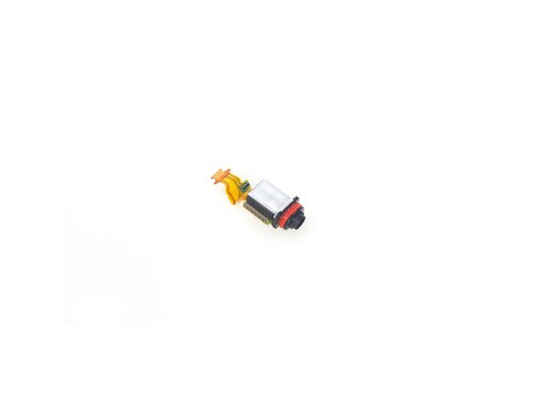
Here is side button flex assembly. It’s integrated by vibration motor, side button connector, fingerprint scanner connector and noise-canceling mic.
-
-
-
The sticker underneath LCD assembly is a little bit strong, so use heat gun to soften it for a few minutes.
-
Remove LCD with digitizer assembly carefully.
-


crwdns2947412:06crwdne2947412:0
The Rear Camers is what rattles if tapped on the corners.
Hi! How could I get more info on the fingerprint scanner? Can it be identified?
Hi iv broken one of the clips on the board that attaches the LCD screen can you get replacement?
My Z5 Compact frame is broken near to the power button (the color part).
Is there any way to buy just the frame?
What is the black layer behind the LCD (which can be seen through squares left for SoC heatsinks). Is it a graphite cooling shield just like it is in XZ Premium?
Hi! I have a Z5 compact with the following issues:
• gyroscope not working
• accelerometer not working
• sim reader not working (with the sim inserted it does not get recognised)
• compass not working (tested through G Maps & GPS Test)
Regarding the sim reader, although complicated and risky, it can be replaced, but when it comes to all the other problems I can’t think of any decent solution.
Do you have any idea about where on the motherboard & what type exactly are the chips responsible for the gyro, accelerometer and compass?
P.S. Buying a new motherboard or another phone is not an option. As I cannot benefit from the warranty of the phone due to the strict location conditions enforced by Sony’s Customer Support program I am looking forward towards improving my soldering skills with this (once) wonderful piece of technology :D