crwdns2942213:0crwdne2942213:0
-
-
This should be easy to remove
-
-
-
In my case the sticky membrane that glues the rubber to the plastic stayed on the plastic.
-
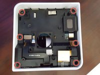
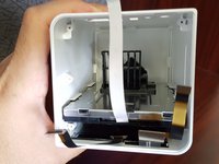
Remove the 4 hex screws that hold the bottom cover to the case
-
-
-
Remove the bottom cover carefully. it should pop right out.
-
-
-
-
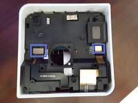
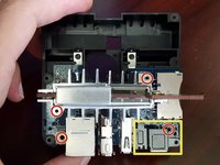
Remove the 6 hex screws attaching the main board enclosure to case
-
Remove connection ribbons that connect to the front LCD screen
-
-
-
Remove the mainboard enclousre from the case by placing your finger in the middle hole and removing it carefully from the case
-
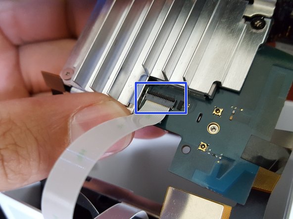
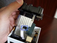
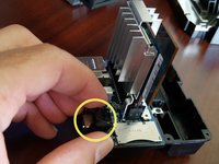
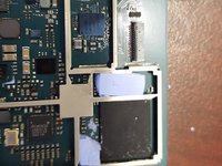
Remove the tape on top of the ribbon connector. this connects to the harddrive
-
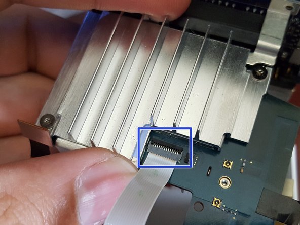
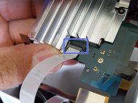
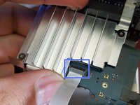
Unlock the connector by flipping the lock back to front. this flap is located closets to the heatsink
-
pull the ribbon cable away from the mailboard
-
-
-
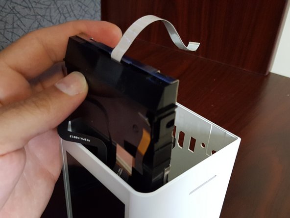
Remove the hard drive by pulling it out
-
-
-
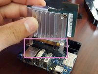
Remove the 4 hex screws, 2x are holding the main board from the expansion board. 1x is holding the sound and power metal shield and 1 is left holding the expansion board from the enclosure.
-
Remove metal audio/power shield
-
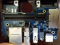
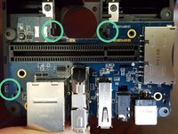
Remove main board from the enclosure board.
-
-
-
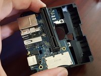
Carefully remove the expansion board away from the enclosure but un clipping it.
-
-
-
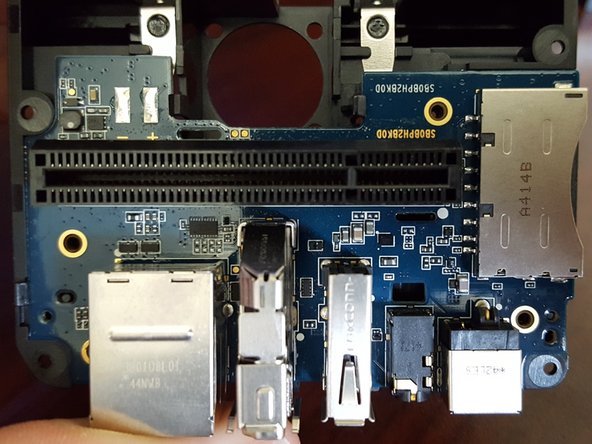
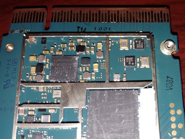
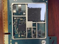
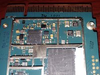
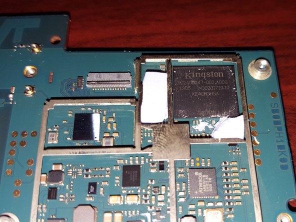
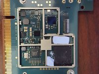
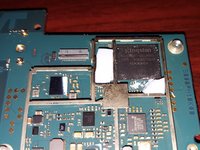
These are pictures of the main board components under the shielding
-
-
-
These are pictures of the main board components under the shielding
-


crwdns2947412:010crwdne2947412:0
Excellent!!! Been looking for this for a while. Too bad someone hasn't hacked the firmware or board to make accesible from the USB port. Anyways I guess I can harvest the 2 TB drive. Thanks again
well done!!! we may need to have video and reusability of the component
or buding software to make local cloud
I am very interested in a hack. Maybe raspberry pi?
I've been trying to figure out a use for the LCD touchscreen of the Lyve Device.... The LCD seems to be a PJ050IA-01J and when I did a search online I found this: http://www.panelook.com/PJ050IA-14A_Inno...
It seems to be a match other than the -14A vs -01J suffix difference...
If I can just figure out the signal interface it would be nice to reuse the screen with some other device like a Raspberry Pi or even an Intel Compute Stick...
Signal Category : MIPI
Signal Class : MIPI (4 data lanes)
Input Voltage for Panel : 1.8/5.4/-5.4V (Typ.)(IOVCC/VSP/VSN)
Interface Type : FPC
Just found this on aliexpress... it seems that the LCD panel is similar to the one used on Doogee X5 Max cellphones... here's a link for the screen
https://www.aliexpress.com/item/Doogee-X...
However the connector doesn't seem to jive...