crwdns2942213:0crwdne2942213:0
-
-
You will only need a PH1 screw driver for this entire teardown.
-
-
-
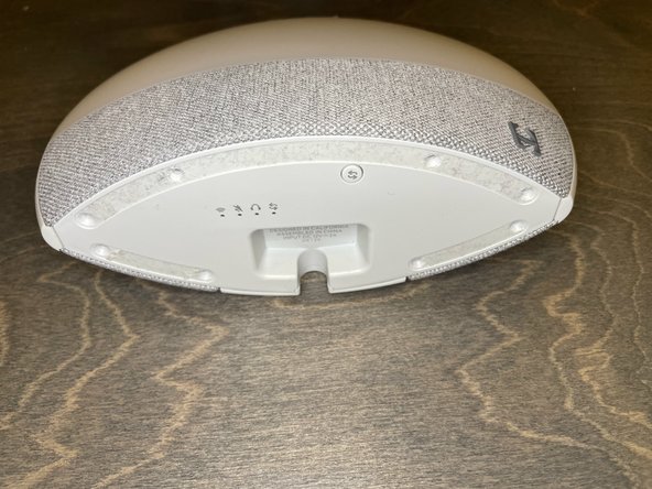
Remove the rubber feet from the bottom of the device.
-
-
-
Pry the bottom cover off using a pry tool.
-
-
-
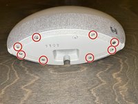
Remove the 6 screws from the circuit board.
-
-
-
-
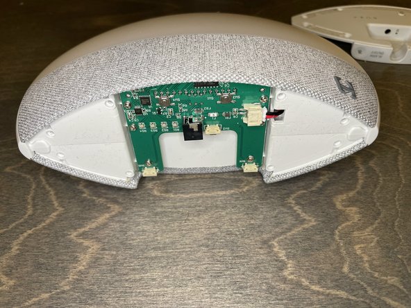
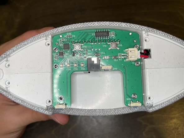
Disconnect the power connector from the circuit board.
-
-
-
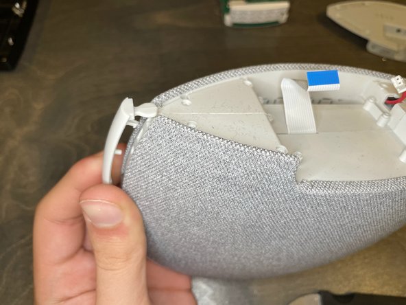
Push the black tabs on the ZIF connector towards the cable, then remove the cable.
-
-
-
Remove the outer button ring using a pry tool.
-
-
-
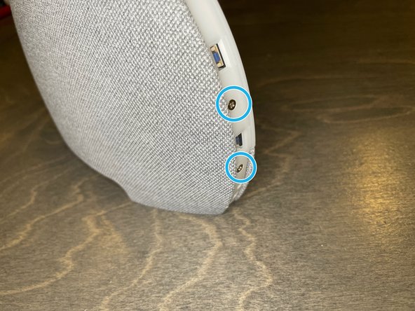
Remove 2 screws from both sides of the device, 4 screws total.
-
-
-
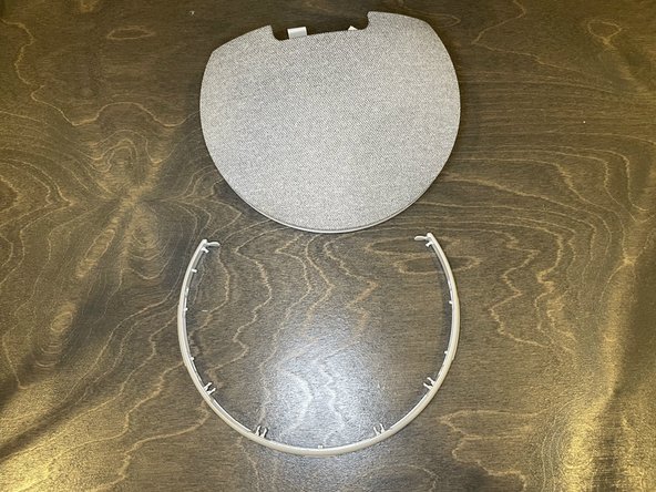
Release the tabs around the ring.
-
Remove the light diffuser.
-
-
-
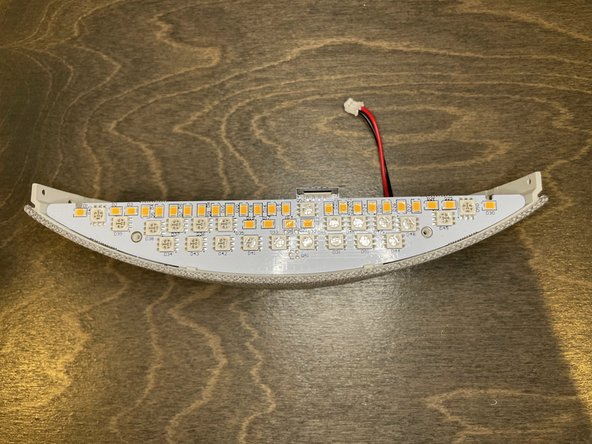
After disconnecting the ribbon cable, we can inspect the LED array.
-
It has both warm and cold colored LEDs.
-
There is a weight glued in below the LED.
-
-
-
Remove these 7 screws.
-
-
-
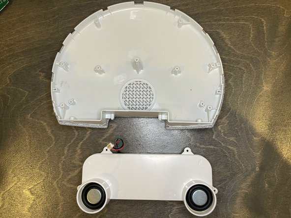
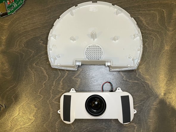
The panel feels heavy and weighted. There is also a weight glued in under the LED array, seemingly in an attempt to make the device feel more premium.
-
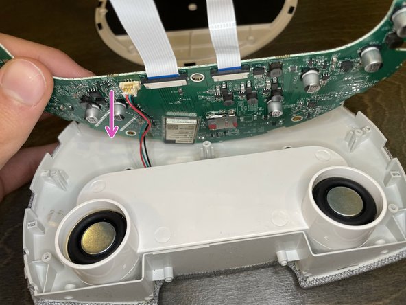
Disconnect the audio cable
-
-
-
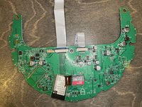
Here we can see the motherboard. It has an ESP32 processor.
-
There is a blank area that could possibly hold a second ESP32
-
There is also a 32GB MicroSD card
-
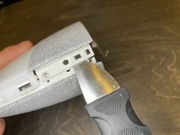
To remove the MicroSD card, stick your nail into the slot on the metal latch, and slide it towards the ESP32.
-
-
-
Remove the 4 screws holding the speaker assembly in place.
-