crwdns2915892:0crwdne2915892:0
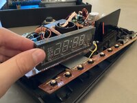
Teardown of a 1976 clock radio. It still works!
-
-
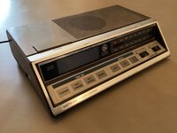
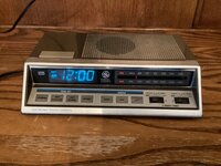
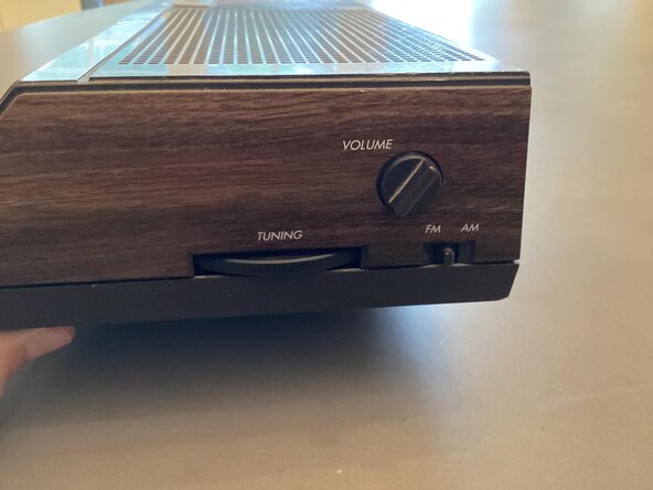
This is a 1976 General Electric Clock Radio. As you can see it still works! The fact that it works demonstrates that vintage devices were made with better quality back then.
-
Inside, it features a Texas Instruments TMS 3455NL microprocessor and a built in AM/FM radio system.
-
-
-
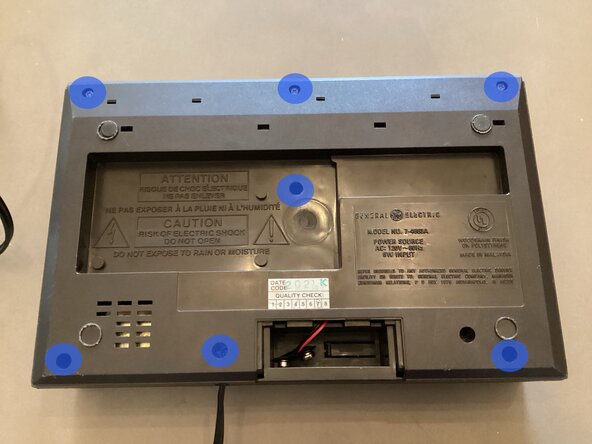
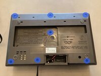
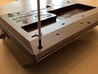
To begin disassembly, 6 Philips head screws need to be removed.
-
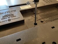
The screws in the middle are very deep inside the device. A long Philips screwdriver is required.
-
-
-
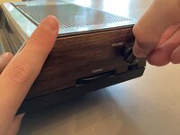
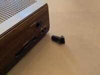
Once all 6 screws are removed, the plastic volume switch cover will need to be removed.
-
To remove the volume switch cover, gently pull it off of the clock radio.
-
-
-
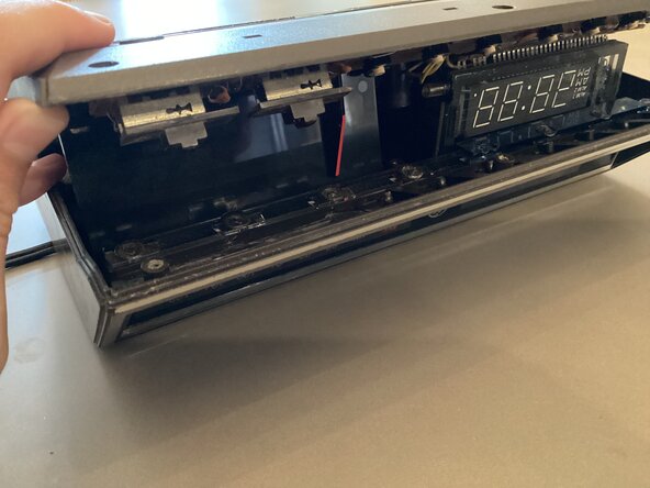
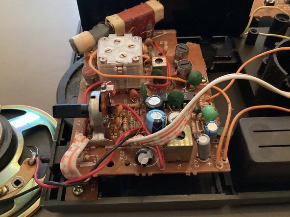
After you have removed the volume switch cover, carefully lift up the bottom cover of the clock radio.
-
The speaker is only attached by the radio being held together, the speaker may fall down unexpectedly if opened wrongly.
-
-
-
-
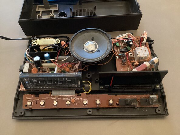
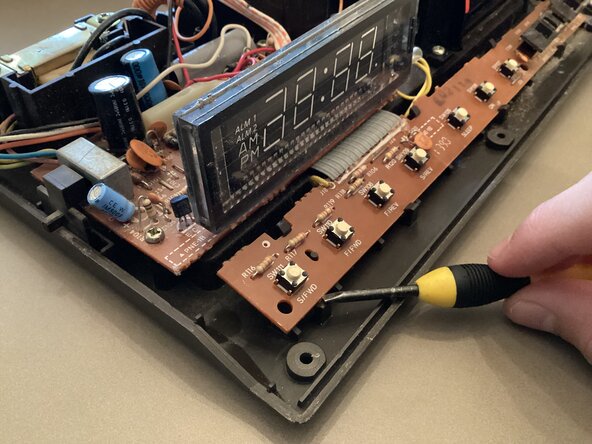
Once, the radio is opened, use a flathead screwdriver to pry away the four clips holding the button PCB in place.
-
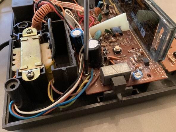
Inside the radio there are high voltage components such as a large transformer and multiple large capacitors, DO NOT TOUCH THEM unless you know they are discharged. You can get very hurt from being shocked by one of these capacitors.
-
-
-
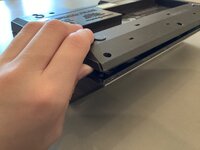
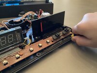
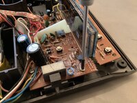
Next, there are four screws holding the main PCB in place. Remove all of them with a Philips screwdriver.
-
(I only show 3 screws being removed but there are four.)
-
-
-
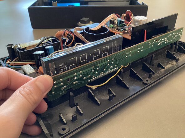
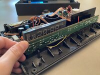
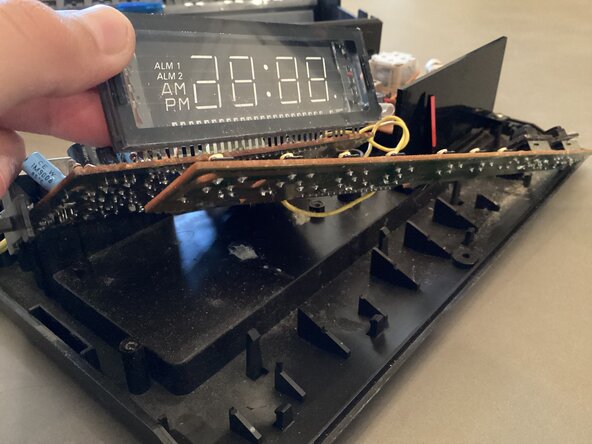
Once all four screws have been removed, lift up the display or the edge of PCB and set it aside.
-
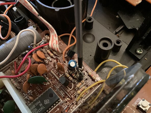
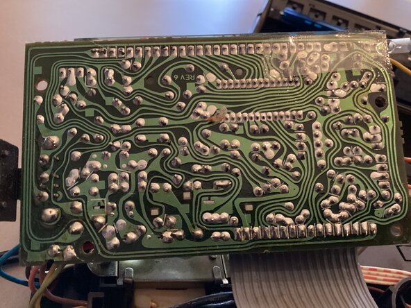
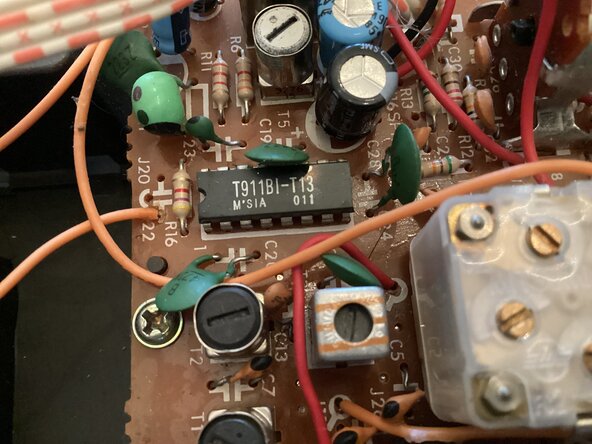
I love seeing hand drawn traces. This clock was made well before CAD software helped PCB development. Someone had to design this entire PCB by hand and probably by themselves.
-
-
-
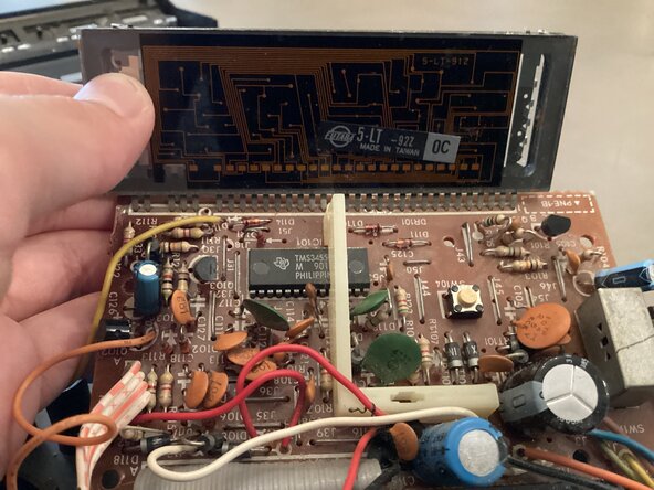
The main PCB connected to the vacuum florescent display is kind of a mess. There are lots of budge wires and components everywhere.
-
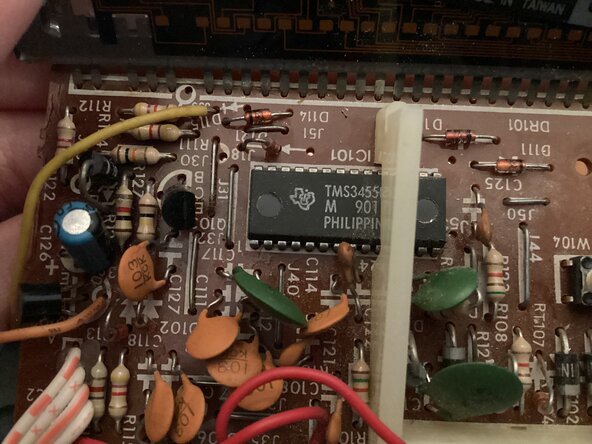
In the center of the PCB under a piece of plastic is a small 32 pin DIP microcontroller. This is the Texas Instruments TMS 3455NL processor.
-
-
-
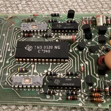
On the other side of the clock radio, there is the radio assembly PCB. It is pretty straightforward and has only basic components, such as an antenna, potentiometer, some capacitors, resistors , and a small microcontroller.
-
(I can’t find anything online about this chip but, it does power the radio assembly PCB.)
-
-
-
Well, this is the end of the teardown. Thanks for viewing if you did:)
-
To reassemble your device repeat these steps in reverse order. DO NOT TOUCH THE CAPACITORS.
-