
Hey musicians! Instead of letting the GAS get the better of you and buying yet another guitar/synth/FX box that you’ll spend time learning and then sell on in a few months, why not invest in a soldering iron?
You don’t have to be rebuilding a tube amp to get a lot of use from a good soldering iron. You can use one to repair guitar jacks, make and mod your own cables, try alternate wiring schemes for your electric guitar, enable cheat modes in some mixers, and repair and replace the USB ports that seem to be the weakest point of much modern music gear.
And while we of course recommend our excellent FixHub and soldering iron for speed, accuracy, portability, and safety (and it’s back in stock in the US!), these general soldering tips will work with any decent gear. Soldering is both a basic skill, and an essential one. Let’s go.

Accessories and Gear
You’re going to need a soldering iron. If you’re reading this, maybe you already have one, in which case it’ll do the job just fine. But like any job, good tools make things a lot easier. I’ll recommend our own FixHub and soldering iron kit, which has several advantages. It heats up instantly, it runs off USB, so you can use it with the FixHub, or with a USB-C PD power brick or power bank. It is also very accurate, temperature-wise, and switches off automatically when you set it down.
Let’s talk accessories. You can rawdog any solder job, but things get way easier if you have a way to hold things in place. You can go for one of those little weighted stands with alligator-clip hands and a built-in magnifier, but I find those are always a fiddle to get things lined up.
A friend of mine uses something called a PCBite, a metal sheet along with a set of cylindrical magnets which stick to the sheet. This lets him clamp all kinds of things in place, and also protects the desktop from molten solder. Another advantage of using big metal chunks to support components is that they wick away heat from where it’s not wanted.
Another options might be heat-resistant finger sheaths, which are particularly handy for fast run-and-gun repairs. You might not want to hold the components you’re actually soldering, but depending on what you’re working with, you might want some extra protection.
Making Cables
As a musician, you probably don’t ever want to add up the money you’ve spent on cables over the years. I always need something a little longer or shorter, or something with a slightly different connector at one end. Making cables is easy, and you can save a ton of cash while also having custom cables to perfectly fit your setup. Guitarists can benefit from reliable patch cables that are made to the exact length to fit the pedals on their pedalboards.
The first step is to buy the right cables and jacks. For guitars, you want something that has a low capacitance. Thanks to the way electric guitars are wired, the cable itself affects the signal, with a higher-capacitance cable acting as a tone control that will bleed off higher frequencies. I like Van Damme cable for its low capacitance, reliability, and price. Then, you’ll need jacks, or XLR plugs (for mics and mixers) that are made for soldering. Bulk buying works out cheaper.
Whatever you choose, the procedure is the same. Cut the cable to length, strip the wires inside, and remember to thread the strain-relief parts of the plugs onto the cable before you solder anything.
For guitarists, this is super easy. You’re soldering mono quarter-inch jacks, which means two wires, and a relatively huge pair of targets onto which to attach those wires. Follow the video to see how it’s done, but the gist is that you need to strip the outer sleeve to reveal the shielding mesh, which you them twist together to make one of the wires. The other wire is in the core of the cable, so strip that back a little less. The art of all cable making lies in getting all these wires to the exact length so they line up with the terminals on the plugs. This keeps everything neat, makes assembling the plug easier, and makes it less likely that one of your wires will catch and break.
The procedure is the same for stereo jack cables, and for smaller 3.5mm jacks. For XLR cables (the ones with three pins that you use with microphones), things are a little tighter but much the same. You may also be dealing with “balanced” cables, which eliminate hum and other interference picked up on long cable runs. This uses a stereo (three-core) cable for a mono signal. It works by flipping the polarity of the spare wire, and combining it with wire carrying the signal. This effectively nullifies anything present in both cables (the hum) without affecting the audio signal. It is as effective as it is ingenious.
As mentioned, the beauty of making you own cables is that you can make them exactly the length you require, with the plugs you need, from 30-meter XLRs with a right-angle plug on one end, to a four-inch patch cable with low-profile jacks for you effects pedals.
Guitar Wiring
Wiring your guitar is at once very simple and quite complex. The physical connections are all straightforward, and with a few tricks (see below) you’ll be in and out in no time. But there are many small tweaks that you can make to the circuit that will have a huge effect on the sound.
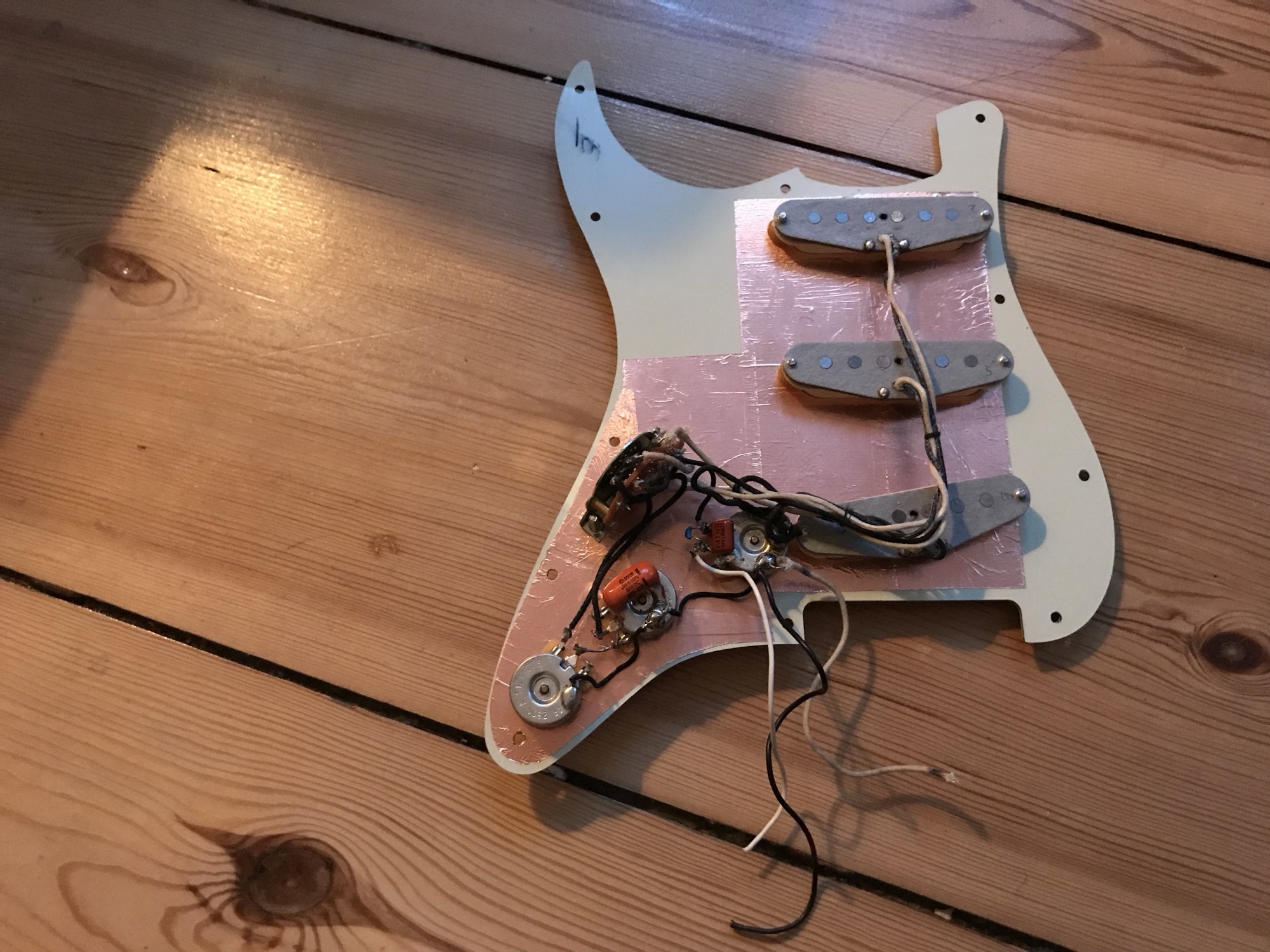
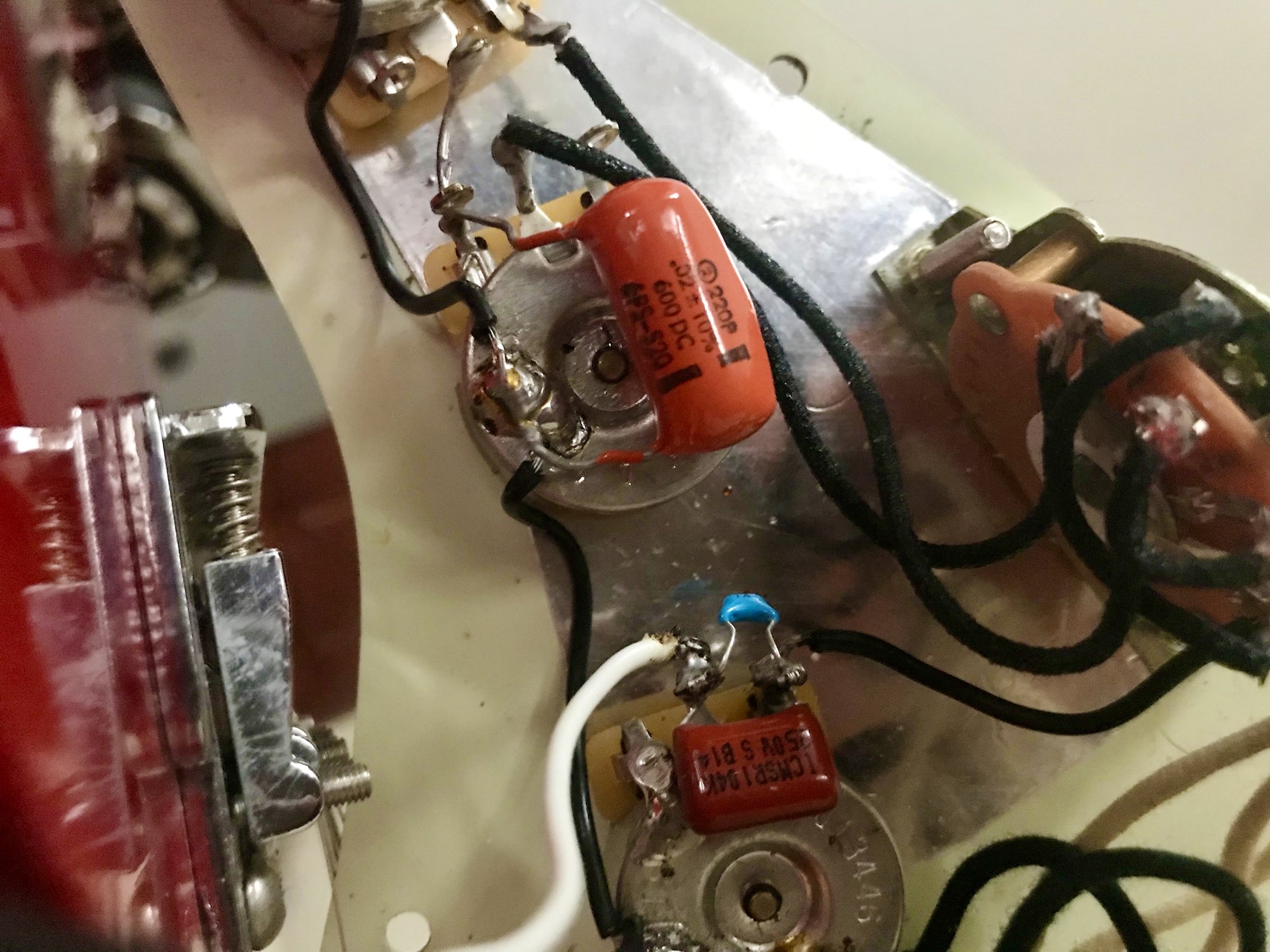
It’s worth a small digression to look at what goes into an electric guitar’s guts. You have the pickups, which are magnets wrapped with thin copper wire that produce a teensy electrical current when you vibrate metal strings near to them. Then there are usually two or more potentiometers, for controlling volume and tone. The volume pot just uses its resistive track to reduce the current running through it. The tone pot adds a capacitor across the terminals, which has the effect of “bleeding off” higher frequencies.
This all then runs to the output jack, usually (as mentioned above) a mono quarter-inch socket.
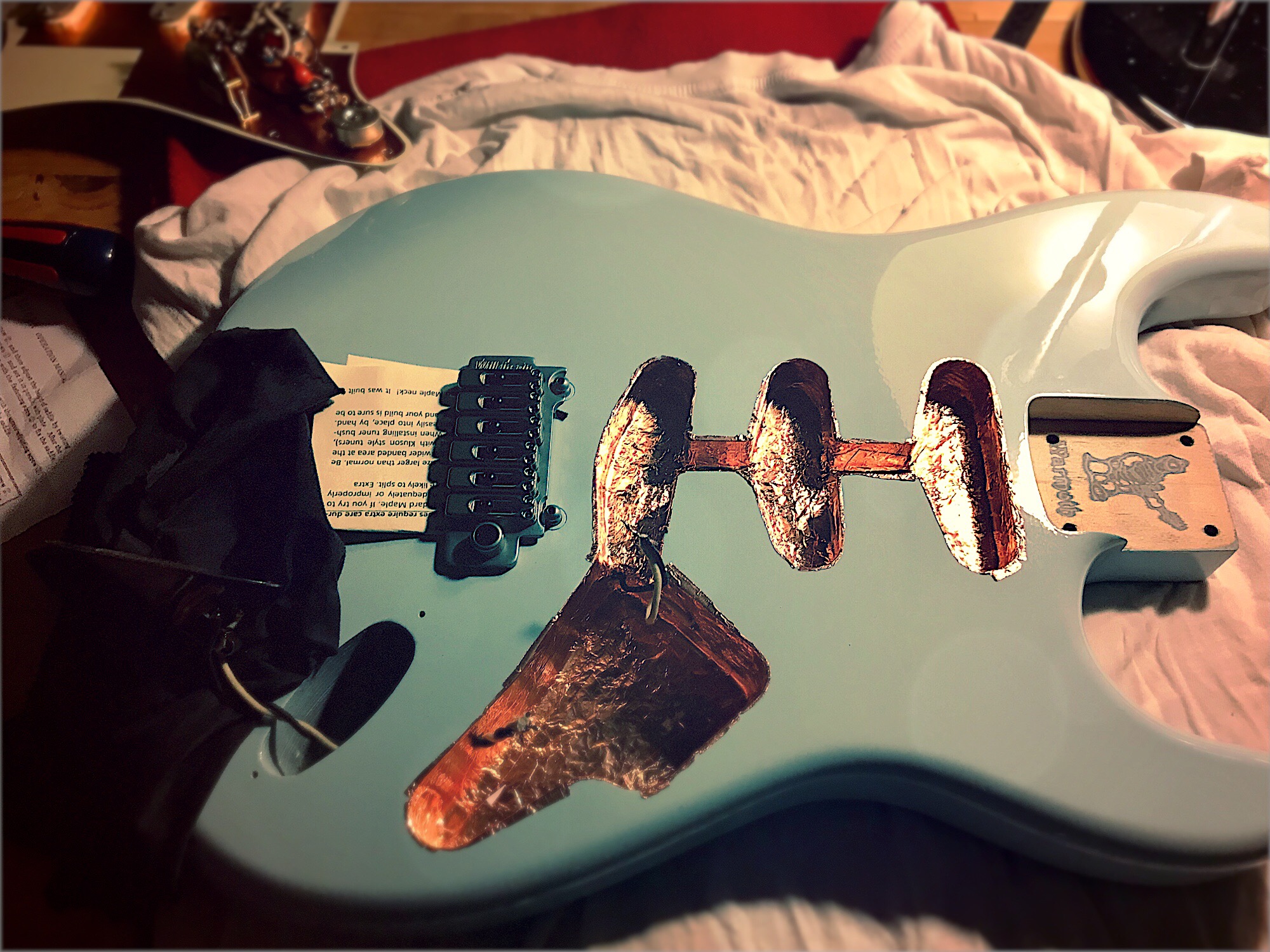
The first important tip for guitar wiring is to protect the guitar’s finish. The wiring from the pickup etc. usually runs through a tunnel in the wood to the output jack, which is too big for the tunnel. After the initial wiring-up, then, everything has to be worked on in-situ, which means laying the pick-guard face-down on the guitar’s surface. I use cardboard to protect the paint from scratches, and to stop solder from blobbing onto it.
Because the pick-guard-mounted components are anchored to the jack, you also don’t have much wiggle-room, especially as guitar-wiring tends to be kept short to avoid picking up interference. Which brings us to the next main point—everything on a guitar is grounded. There will even be a wire running from the bridge (which itself touches the strings) to ground. Otherwise, you’re going to get hum.
The soldering itself is straightforward, once you have decided on a wiring scheme, with one exception. You will be soldering wires to some big hunks of metal, which are heatsinks that wick away heat. This is bad news for potentiometers, which are easily damaged by overheating.
The trick is to use more power. Guitar mod guru Dirk Wacker recommends using a 30-watt iron for most guitar work, with a 60-watt iron for soldering pots. The extra power heats a spot on the pot faster, allowing you to solder, and get out quickly. With lower power, the pot’s metal casing conducts the heat away before it can get up to temperature.
The iFixit soldering iron can output up to 100 watts, making it ideal for all guitar-related repairs.
Danger and Care
Speaking of capacitors, here’s a very important warning. The tone circuit mentioned above uses a secondary characteristic of a cap: to remove higher frequencies from an electrical signal. But the main use of a capacitor is to store electricity, and that’s how it is used in guitar amplifiers. And a capacitor can discharge that electricity fast. Like, pretty much instantly, which means that if you touch it when it is charged, you’re going to get a potentially lethal jolt. This isn’t just a theoretical warning to be careful. You can die if you poke a charged cap in an amp.
The answer is to discharge those capacitors, which is beyond the scope of this already lengthy soldering article. Only then will you know it’s safe to work inside an amp. And remember, those capacitors keep their charge even after the amp has been switched off for a while.
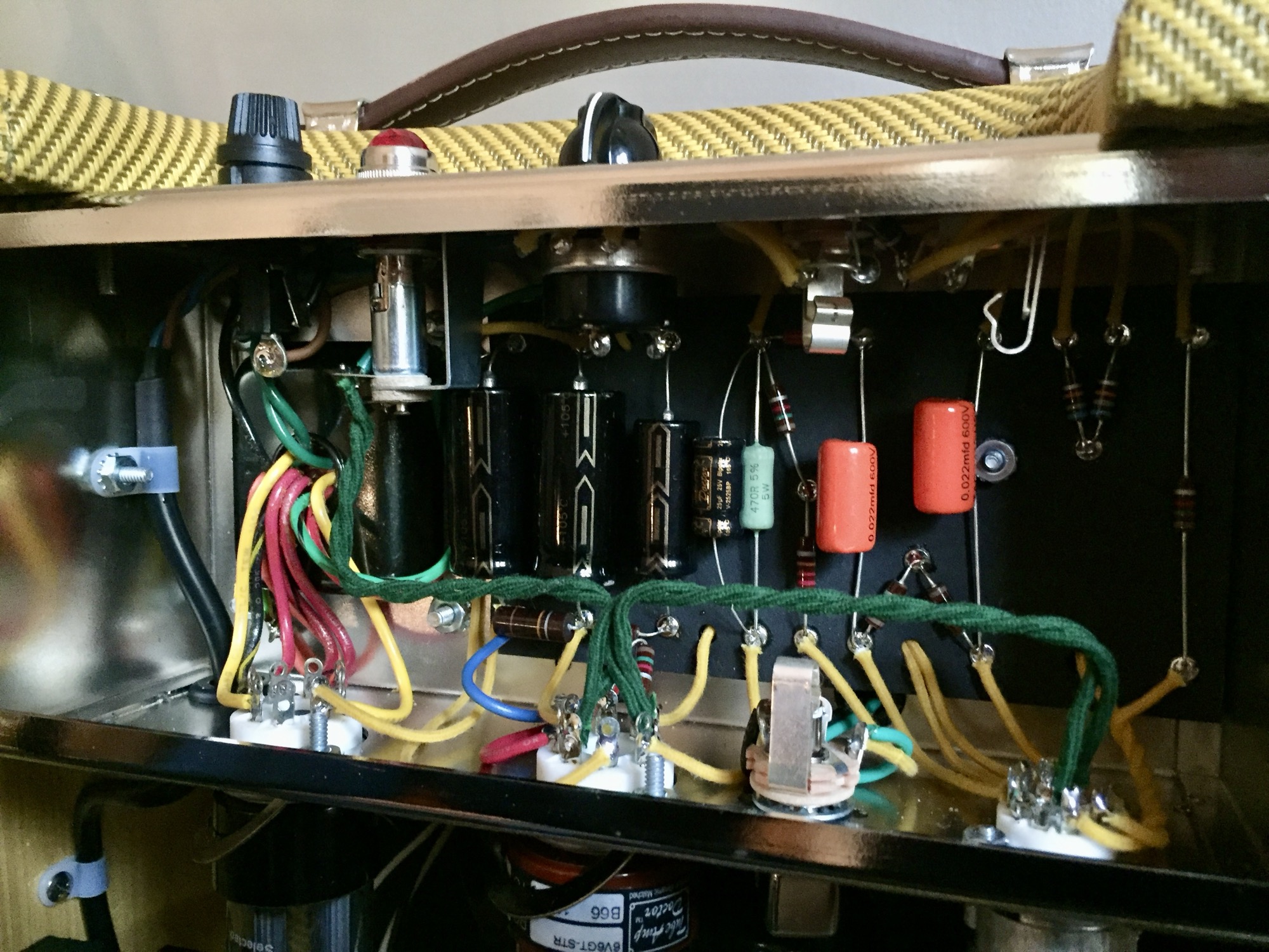
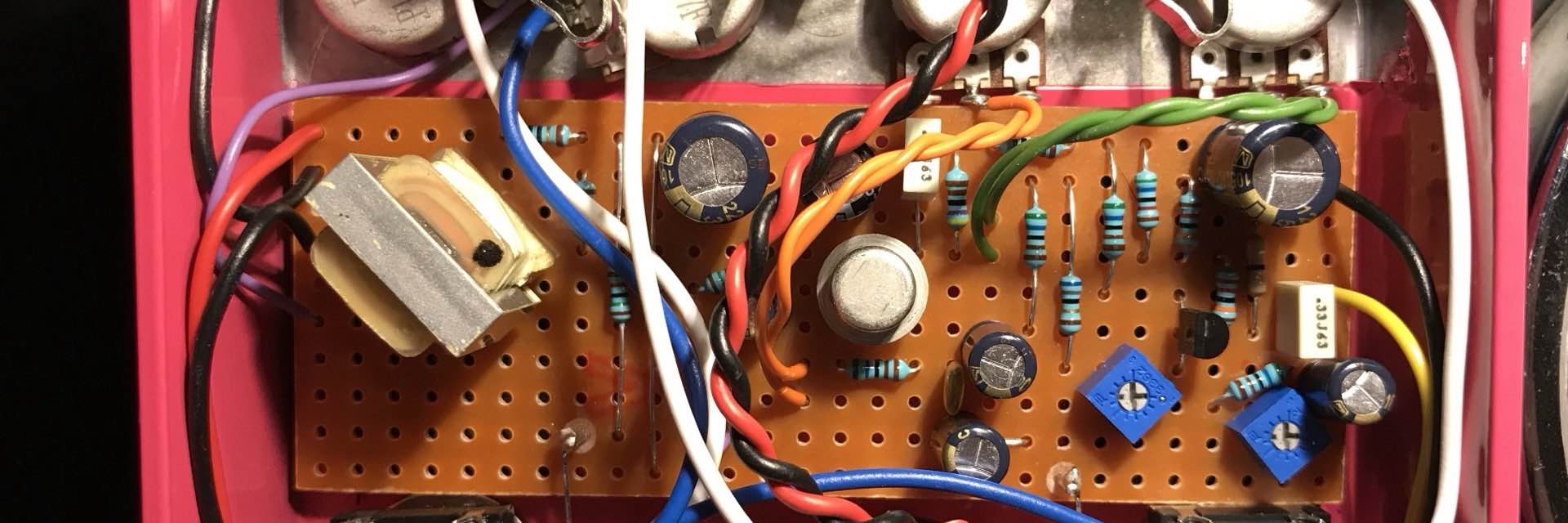
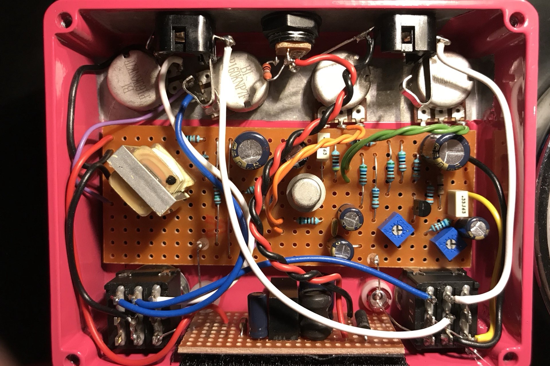
Other than that, working inside an amp is even easier than working inside a guitar, mostly because you have more space. If it’s a tube amp, or a solid-state-but-not–yet-a-computer amp, then it will likely have been put together by hand, and can easily be repaired by your hand.
One other important note. You may notice that the wiring in that vintage tube amp is neat. It’s not just for aesthetics. Keeping wires short minimizes the possibility of picking up electromagnetic interference. You should also pay attention to any twisted pairs of wires. If you run power and ground wires parallel to each other, then they can turn into a kind of loop antenna, which picks up magnetic noise. Twisting them helps to cancel out any picked-up interference, as well as reducing the space for it to occur in the first place.
Do not twist your signal wires together though, because the signal can induce a current in the ground which can lead to hum and feedback.
Modding Cables
Once you’re comfortable soldering cables and jacks, you might start to look at old discarded cables as a resource, and not a potential tangle-enabler. Do you need an XLR to 1/4-inch jack cable? Just mod the cables you already have. What if you have the right cable already, only it’s way too long? Just shorten it to fit.
Sometimes, a cable will stop working, and you’ll check the plugs only to see that they’re just fine. In this case, it’s probably the cable itself that’s broken somewhere along the line. Don’t toss it though. Just cut it in half, and test each side for continuity with you multimeter. Set the good half aside, and split the bad half again. Keep going until you’re down to your last six inches or so, and recycle the problem section. Now you have several different lengths of known-good cable, plus two plugs or jacks to reuse.
And it’s not just cables that can be modded. If you play the guitar, then there’s a whole lot of modding that can be done just by swapping a few wires, or changing the values of capacitors. Let’s get into the esoteric world of circuit modding.
Wiring Schemes for Guitar Circuits
As discussed, the wiring inside an electric guitar is simple, but because of the way it all works, it’s possible to make big changes to the sound with small tweaks. In an all-analog setup, the amp’s circuit combines with the guitar’s circuit, with various loads and impedances affecting each other. The copper wire windings on the pickups become part of the same circuit as the amp’s caps and tubes.
That’s an interesting subject in itself, but for our purposes, let’s look at a couple of examples of what you can do to your simple circuit to change the sound.
My favorite is what has come to be called “50s wiring.” In a guitar circuit, the volume and tone potentiometers are identical. They’re used as variable resistors. In the case of volume, part of the signal is sent to ground, and therefore discarded. For tone, the pot sends part of the signal to ground. The cut-off point of the high frequencies that are bled off depends on the value of the resistor.
There are several ways to connect the volume and tone pots together, and this is the heart of “50s wiring,” as compared to “”60s wiring,” and “modern wiring.”
In modern wiring, the output of the tone pot is connected to the input of the volume pot. For the full explanation see this excellent article by Dirk Wacker, but the short version is that this causes the tone to get “darker” (less treble) when you turn down the volume.
In 50s wiring, you connect the tone pot’s output to the volume pot’s output instead of its input. This prevents the volume pot from affecting the tone, but it also makes the guitar sound clearer overall. I use this on my guitar. And if you’re feeling fancy, you could add a switch to swap wiring schemes on the fly.
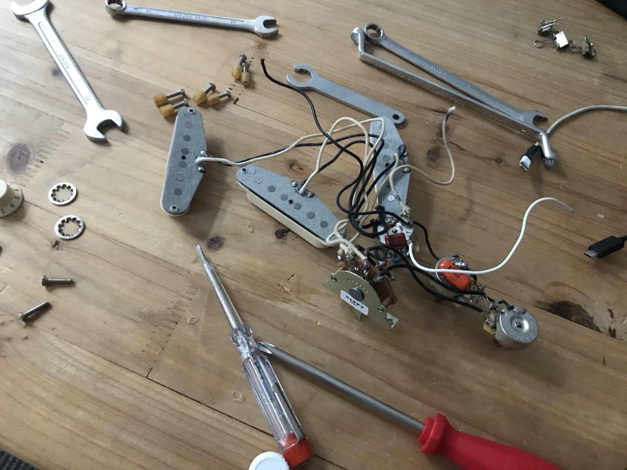
Another easy mod is to add a bass-cut control. The Fender Stratocaster (as seen in several of the pictures of my guitar in this article) has three knobs. Normally one of the pots is for volume, and the other two control the tone of the three pickups, in two groups.
With the bass roll-off, you rewire one of those tone controls, using the capacitor to remove bass frequencies. In conjunction with the regular tone knob you get way more control over the sound. And cutting the bass lets you finesse the amount of distortion you get from a cranked amp, with a minimal effect on the volume.
Replacing USB Sockets
OK, we’ve veered off into guitar mods, but it was worth it to see just how useful—and fun—a little soldering can be. But there’s also plenty you can do to fix more modern electronics.
One very useful skill is being able to replace a USB socket. These can be a weak point on music gear, nowhere near as robust as a 1/4-inch jack (originally designed for being endlessly replugged by telephone operators to route calls).
A well-designed circuit, like that of the Teenage Engineering OP-1, might put the I/O on a separate, easily-accessible circuit board for easy replacement. But even when the USB and 3.5mm audio jack sockets are soldered direct to the main board, it’s a straightforward fix.
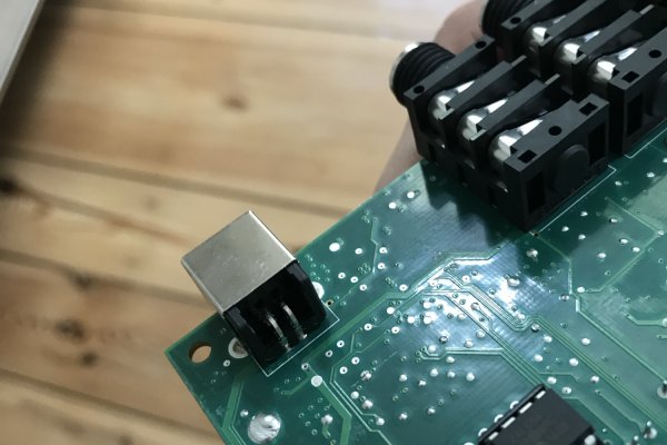
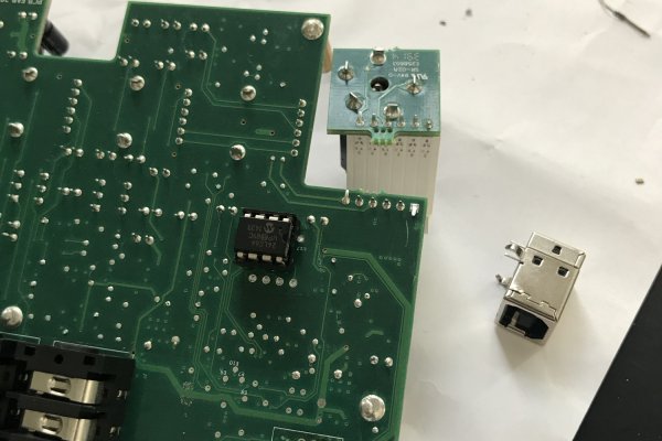
USB-A and USB-B (the printer-cable one) are easy, because they’re big, and they only have four connections to solder, plus a couple of lugs to help things in place. In the case of USB-B, there will be four prongs that slot through four holes in the board. USB-A ports will have the prongs at the back, or underneath the connector. To replace one you’ll need to buy a connector, remove the existing solder, probably with a desoldering wick, and then solder the new part into place.
The hardest part of all this will probably be gaining access to the board to perform the repair, but even the fanciest music gear is dead simple compared the the easiest smartphone repair.
USB-C is a bit trickier, mitigated somewhat by the fact that, in my experience so far, USB-C ports tend to be a bit more robust that microUSB, for example. Once you have removed the broken USB-C port and cleaned up the old solder, you may need to apply a tiny amount of fresh solder to each of the pins on the board, and then use a heat gun to reflow the solder onto both the connecting pins and the pins that secure the socket to the board.
Or you may have to use a soldering iron to individually re-solder or reflow each pin. In the end though, the process is the same, just smaller and fiddlier. It’s totally do-able by anyone with a bit of soldering experience.
To sum up, a soldering iron is an essential tool for the musician, whether you’re playing synths or more old-fashioned instruments. And even if you use a computer and Ableton for absolutely everything, there are still plenty of computer repairs that use soldering.


crwdns2944067:00crwdne2944067:0