crwdns2935425:04crwdne2935425:0
crwdns2931653:04crwdne2931653:0


Removing Extra Components
-
Remove the screws in the three red circles.
-
Two of the three ribbon cables in the orange box will need to be removed like those above the battery. Use the pointed edge of a spudger to pull the third cable out to the left.
-
Insert the spudger on top of the ribbon cable but below the circuit board in the yellow circle, and pry that ribbon cable free. Remove the headphone jack as see in the picture.
-
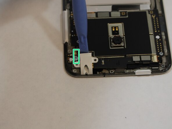
Use tweezers to disconnect the wire connector in the green box.
-
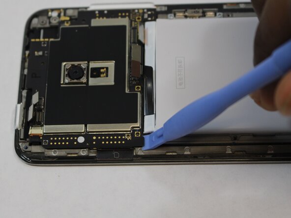
As seen in the third picture, gently insert the plastic opening tool and unhook that cable and begin to lift the circuit board.
| [title] Removing Extra Components | |
| - | [* black] Remove the screws in the three red circles. Two of the three ribbon cables in the turquoise box will need to be removed like those above the battery. Use the pointed edge spudger to pull the third cable out to the left. |
| - | [* black] Insert the spudger on top the ribbon cable but below the circuit board in the yellow circle, and pry that ribbon cable free. Remove the headphone jack as see in the picture. |
| - | [* black] Use tweezers to disconnect the wire connector in the red box. As seen in the picture gentle insert the plastic opening tool and unhook that cable and begin to lift the circuit board. |
| + | [* red] Remove the screws in the three red circles. |
| + | [* orange] Two of the three ribbon cables in the orange box will need to be removed like those above the battery. Use the pointed edge of a spudger to pull the third cable out to the left. |
| + | [* yellow] Insert the spudger on top of the ribbon cable but below the circuit board in the yellow circle, and pry that ribbon cable free. Remove the headphone jack as see in the picture. |
| + | [* green] Use [product|IF145-020|tweezers] to disconnect the wire connector in the green box. |
| + | [* black] As seen in the third picture, gently insert the plastic opening tool and unhook that cable and begin to lift the circuit board. |
crwdns2944171:0crwdnd2944171:0crwdnd2944171:0crwdnd2944171:0crwdne2944171:0