crwdns2935425:08crwdne2935425:0


-
Let's take a quick break from disassembly to investigate the circuit board.
-
The yellow box is the power supply circuitry. It provides the three regulated and one unregulated rail used by the device.
-
The red box shows the high speed high voltage relays. These switch between ranges. They make a nice soft ping when they activate.
-
The orange section is the multiplexer, most function switching occurs here. The large white square is a high voltage precision matched resistor divider from Craddock
-
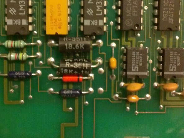
The blue and green boxes hold the -4.2V and -6.4V references respectively. The 6.4V zener (1N4579, shown in image 2) is small, orange and VERY expensive
-
The purple box shows the multi-slope integrator circuit. The white box is the integrating capacitor
-
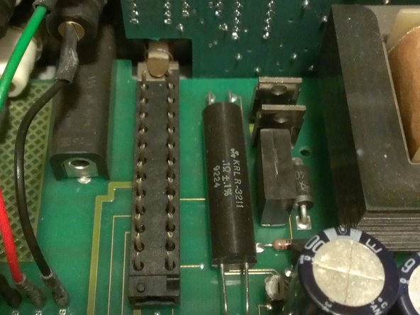
Lastly, the black cylinder with four wires going to it is a special four-wire resistor used in precision current measurements.
crwdns2944171:0crwdnd2944171:0crwdnd2944171:0crwdnd2944171:0crwdne2944171:0