crwdns2935425:08crwdne2935425:0


-
Replace the new mounts onto the respective corner of the back of the printed circuit board, and while it's laid flat, tighten a screw into the corner through the mount and the printed circuit board to hold the trigger assembly in place.
-
Start laying the top of the printed circuit board back onto the front of the controller, and reattach the trackpad ribbon cables carefully.
-
Ensure that the button mesh and the release lever popper at the bottom are laid in place.
-
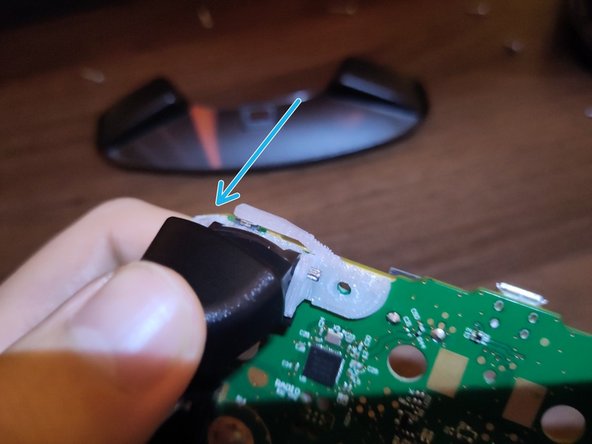
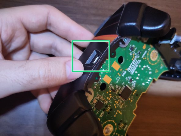
Lift up the top of the circuit board, and replace the USB port cover two-piece over the top of the printed circuit. Ensure that it goes over the bumper levers of the trigger mounts, and that the micro USB port is flush.
-
Replace the four T6 screws attached to the trigger mounts and the back of the PCB through the front chassis.
crwdns2944171:0crwdnd2944171:0crwdnd2944171:0crwdnd2944171:0crwdne2944171:0