crwdns2935425:04crwdne2935425:0
crwdns2931653:04crwdne2931653:0


Remove screen assembly
-
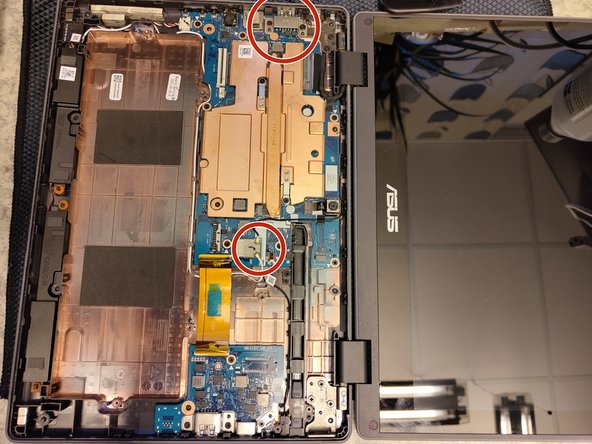
Remove two screws holding down a USB-A cover. The lower one in the picture is a M2.0 and the upper is a M2.5. Then remove the metal cover.
-
Remove display ribbon cable. There is a latch under the plastic film.
-
The black antenna connector (white is removed in the next step) has a hard plastic cover, lift it slowly from the network-chip cover to not delaminate the metal cover from the chip. Follow the cables through the guided fits.
-
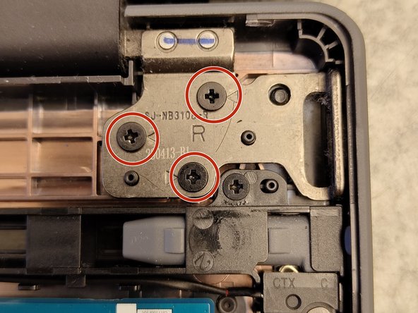
Remove the remaining 5 screws (2 on the left side and 3 on the right) holding down the screen assembly to the backplate and motherboard assembly. Marked with debossed triangels in the metal.
crwdns2944171:0crwdnd2944171:0crwdnd2944171:0crwdnd2944171:0crwdne2944171:0