crwdns2935425:06crwdne2935425:0
crwdns2931653:06crwdne2931653:0


-
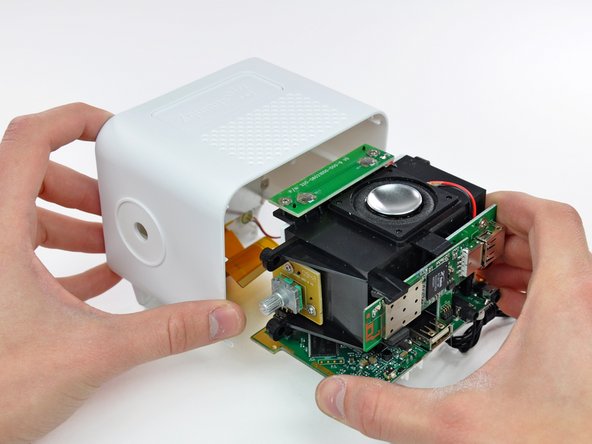
After removing four Phillips screws securing the inner chassis to the outer case, the guts can be removed in one piece.
-
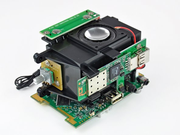
Controls are routed through two daughterboards; one houses the two push-button elements and the other holds the volume dial.
-
The wireless card is attached to a small interconnect board, converting the four-pin connector found on the logic board into the USB connector used by the wireless card.
-
After a bit too much wiggling, we broke the FM antenna lead where it attaches to the board. Soldering iron to the rescue!
crwdns2944171:0crwdnd2944171:0crwdnd2944171:0crwdnd2944171:0crwdne2944171:0