crwdns2933423:0crwdne2933423:0

Conjunto de LED Glyph

crwdns2931529:0crwdnd2931529:0crwdnd2931529:0crwdnd2931529:06crwdnd2931529:0crwdne2931529:0

crwdns2936315:0crwdne2936315:0
crwdns2936331:0crwdne2936331:0
crwdns2931653:027crwdne2931653:0
LED Glyph Assembly, Pry up the motherboard cover: crwdns2935265:00crwdnd2935265:01crwdnd2935265:03crwdne2935265:0 LED Glyph Assembly, Pry up the motherboard cover: crwdns2935265:00crwdnd2935265:02crwdnd2935265:03crwdne2935265:0 LED Glyph Assembly, Pry up the motherboard cover: crwdns2935265:00crwdnd2935265:03crwdnd2935265:03crwdne2935265:0
Pry up the motherboard cover
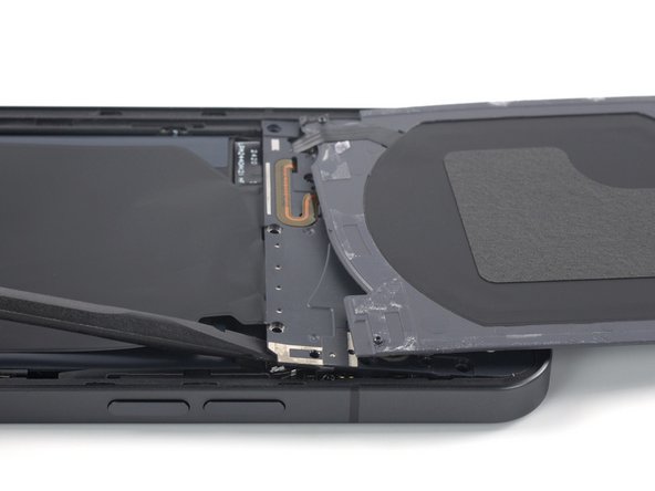
  • Carefully fold the charging coil to the top edge of the phone to access the bottom edge of the motherboard cover.

  • Insert the flat end of a spudger underneath the bottom right edge of the motherboard cover.

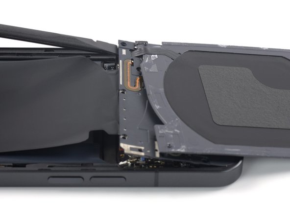
  • Pry up with the spudger to release the motherboard cover from its clips.

  • Repeat the prying procedure for the bottom left edge of the motherboard cover.

Dobla con cuidado la bobina de carga hacia el borde superior del teléfono para acceder al borde inferior de la cubierta de la placa base.

Introduce el extremo plano de un spudger por debajo del borde inferior derecho de la tapa de la placa base.

Haz palanca con el spudger para liberar la cubierta de la placa base de sus clips.

Repite el procedimiento de apalancamiento para el borde inferior izquierdo de la tapa de la placa base.

crwdns2944171:0crwdnd2944171:0crwdnd2944171:0crwdnd2944171:0crwdne2944171:0