crwdns2935425:07crwdne2935425:0
crwdns2931653:07crwdne2931653:0

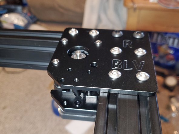


Right Corner
-
In a CoreXY setup both X and Y stepper move together. Technically the top left stepper is the X and the top right stepper is the Y
-
The right corner is assembled in virtually the same manner as the left. However I tried doing it in the same manner as the videos posted on the project page
-
Attach the top plate to the frame with 2x M6x10mm button head screws, 6x M5 T-nuts and 6x M5x8mm button head screws. Tighten the screws completely.
-
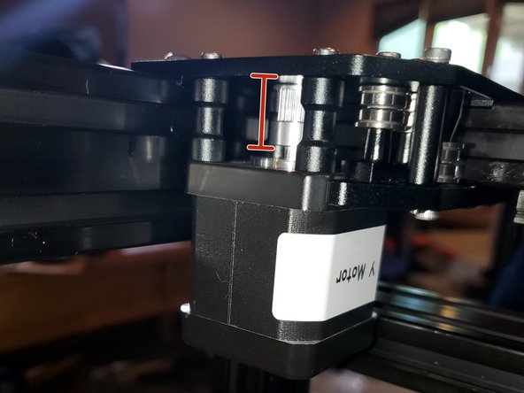
Insert 3x M3x25mm socket head screws into the stepper mounts. Slide 3x 19mm standoffs over the screws than thread the M3x25mm into the stepper motor but do not tighten.
-
The plug on the stepper motor should be facing towards the X motor
crwdns2944171:0crwdnd2944171:0crwdnd2944171:0crwdnd2944171:0crwdne2944171:0