crwdns2935425:010crwdne2935425:0


-
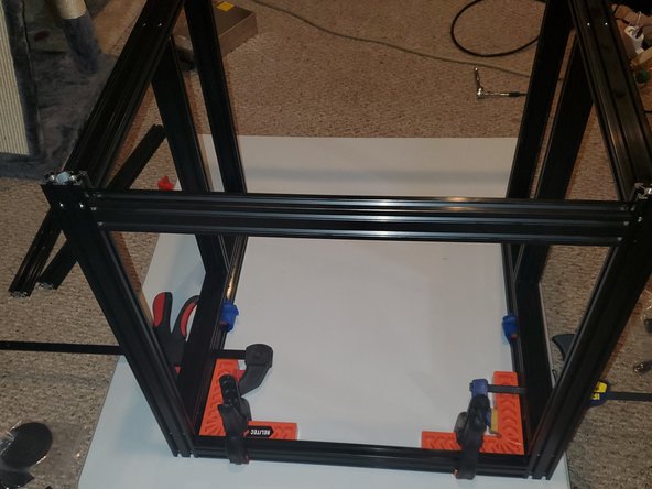
The main picture is of the assembled frame upside down with the front opening closest to you
-
Take the 3x remaining 496mm 2040 and thread 12x M6x16 button head screws into the threaded holes leaving 2-3mm of head clearance.
-
Identify the front corners. Along the front there will only be 1x 496mm 2040 along the bottom of the front of the printer
-
Using your corner jigs clamp the left side, right side and cross supports together.
-
To make it easier because I was doing the cross beam for the back top first I slid the 496mm 2040 that was for the front bottom to the front top(where the orange circles are) and tightened the button head screws.
-
Once the back top was done I tightened the back bottom. The 496mm 2040 should be 20.2mm from the edge(blue line)
-
With the back complete, loosen the 496mm 2040 cross support and move it from the front top to front bottom. Make sure the blue line gap is 20.2mm. When everything is square and the dimensions are correct tighten down the 4 button head screws
crwdns2944171:0crwdnd2944171:0crwdnd2944171:0crwdnd2944171:0crwdne2944171:0