crwdns2933423:0crwdne2933423:0

Jura Capresso IMPRESSA J5 demontage

crwdns2931529:0crwdnd2931529:0crwdnd2931529:0crwdnd2931529:02crwdnd2931529:0crwdne2931529:0

crwdns2936315:0crwdne2936315:0
crwdns2936313:0crwdne2936313:0
crwdns2931653:015crwdne2931653:0
Jura Capresso IMPRESSA J5 Teardown: crwdns2935265:00crwdnd2935265:01crwdnd2935265:03crwdne2935265:0 Jura Capresso IMPRESSA J5 Teardown: crwdns2935265:00crwdnd2935265:02crwdnd2935265:03crwdne2935265:0 Jura Capresso IMPRESSA J5 Teardown: crwdns2935265:00crwdnd2935265:03crwdnd2935265:03crwdne2935265:0
  • "Tamping Assembly"

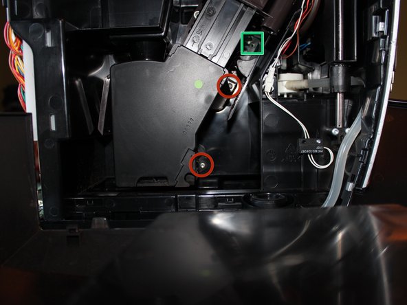
  • I call the black plastic diagonal assembly with the brown top the "tamping assembly". It receives the ground coffee, forms the puck, holds the puck while the water/steam goes through it, and then drops it in the waste tray (I presume).

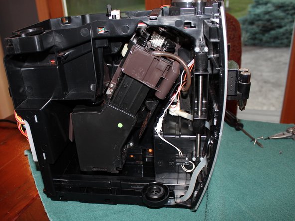
  • Note If you choose to remove the tamping assembly you should carefully note where the brown portion is on the larger centre plastic screw. Maybe take a picture, or count exactly how many threads are above the brown portion.

  • When you reassemble, this it needs to be in the exact orientation it was in when you took it apart or it might break the machine. I realised it was a timing mechanism after having taken it apart and misaligned it. Luckily I had pictures to help get it back to the starting position.

  • Remove the three T15 screws marked with the red circles. Top two are fine thread and bottom course thread. Note the screw marked with a blue sqaure does not need to be removed to remove the tamping assembly.

  • Also note the unused screw hole marked with a green square. You might need a long handled screw driver or an extension bit.

Brouwunit demontage.

De brouwunit ontvangt de gemalen koffie, vormt de puck, houdt deze op zijn plaats terwijl het hete water erdoor stroomt en werpt de puck uit.

Opmerking: Als je de brouwunit wilt verwijderen, moet je precies noteren waar het bruine gedeelte op de grote plastic schroef zit. Maak een foto of tel hoeveel gangen er uitsteken.

Bij het opnieuw monteren moet het in dezelfde positie staan als bij het verwijderen, anders kan er schade ontstaan. Ik heb ooit een probleem met de synchronisator ontdekt toen ik hem niet goed had geplaatst. Gelukkig had ik een foto en kon ik de beginpositie correct instellen.

Verwijder de drie rood gemarkeerde Torx T15-schroeven. De bovenste twee hebben een fijne schroefdraad, de onderste een grove. De blauw gemarkeerde schroef hoeft niet te worden losgedraaid om de zetgroep te verwijderen.

Let op het ongebruikte schroefgat dat groen gemarkeerd is. Voor de andere gaten heb je een schroevendraaier of bithouder met een lange schacht nodig.

crwdns2944171:0crwdnd2944171:0crwdnd2944171:0crwdnd2944171:0crwdne2944171:0