crwdns2935425:017crwdne2935425:0


-
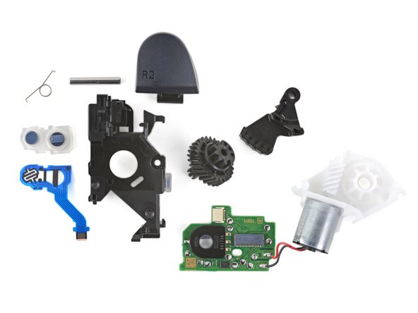
Let's take a quick deep dive on these triggers:
-
First up, the button sensors—R1 on the left and R2 on the right. R2 seems to use a "two-stage" sensor to differentiate partial and full trigger pulls, while R1 is a plain-Jane digital switch.
-
Next, the plastic frame, metal pin, and spring. These pieces perform the non-adaptive R2 trigger action, without the rest of the fancy parts.
-
The gear system works together as demonstrated in the previous step: the white worm gear (from the green bullet below) spins the circular gear, which drives the arm up to resist R2's lever action.
-
The white gear housing holds all the gear components together. The silver motor sticking out the bottom drives the worm gear. Its leads are soldered to the trigger module's circuit board (up next).
-
Finally, a circuit board to bring it all together! There are two ribbon cable connections: one to the buttons, and one to the motherboard. The black encoder measures the rotation of the circular gear from the yellow bullet.
crwdns2944171:0crwdnd2944171:0crwdnd2944171:0crwdnd2944171:0crwdne2944171:0