crwdns2933423:0crwdne2933423:0

Smontaggio PlayStation 5

crwdns2936315:0crwdne2936315:0
crwdns2936321:0crwdne2936321:0
crwdns2931653:017crwdne2931653:0
PlayStation 5 Teardown: crwdns2935265:00crwdnd2935265:01crwdnd2935265:03crwdne2935265:0 PlayStation 5 Teardown: crwdns2935265:00crwdnd2935265:02crwdnd2935265:03crwdne2935265:0 PlayStation 5 Teardown: crwdns2935265:00crwdnd2935265:03crwdnd2935265:03crwdne2935265:0
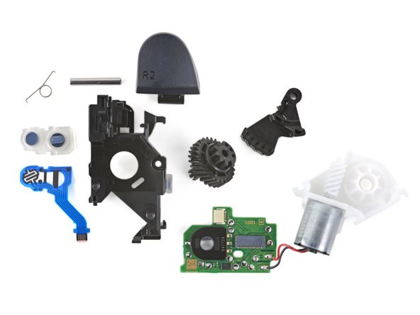
  • Let's take a quick deep dive on these triggers:

  • First up, the button sensors—R1 on the left and R2 on the right. R2 seems to use a "two-stage" sensor to differentiate partial and full trigger pulls, while R1 is a plain-Jane digital switch.

  • Next, the plastic frame, metal pin, and spring. These pieces perform the non-adaptive R2 trigger action, without the rest of the fancy parts.

  • The gear system works together as demonstrated in the previous step: the white worm gear (from the green bullet below) spins the circular gear, which drives the arm up to resist R2's lever action.

  • The white gear housing holds all the gear components together. The silver motor sticking out the bottom drives the worm gear. Its leads are soldered to the trigger module's circuit board (up next).

  • Finally, a circuit board to bring it all together! There are two ribbon cable connections: one to the buttons, and one to the motherboard. The black encoder measures the rotation of the circular gear from the yellow bullet.

Un'immersione rapida in questi trigger:

Partiamo dai sensori sotto il pulsante, R1 a sinistra e R2 a destra. R2 sembra utilizzare un sensore "a doppio stadio" per distinguere tra pressione parziale e totale sul grilletto, mentre R1 ha uno switch digitale molto ordinario.

Passiamo al telaio di plastica, alla barretta metallica e alla molla. A questi pezzi è affidata l'azione non adattiva del grilletto R2, in assenza di intervento della parte più avveniristica.

Il sistema a ingranaggi funziona come dimostrato nel passo precedente: la vite senza fine bianca (vicino al circolino verde) fa girare la corona dentata, che spinge il braccio verso l'alto per resistere all'azione di leva del pulsante R2.

Il gruppo bianco che contiene gli ingranaggi tiene insieme tutte le componenti. Il motore che sporge dalla parte inferiore fa girare la vite senza fine. I cavetti di alimentazione sono saldati alla scheda del modulo del trigger.

E infine, il circuito stampato che fa funzionare tutto insieme! Ci sono due cavi a nastro: uno che collega i pulsanti e uno che porta alla scheda madre. Il rilevatore nero misura la rotazione della ruota dentata circolare evidenziata con il circolino giallo.

crwdns2944171:0crwdnd2944171:0crwdnd2944171:0crwdnd2944171:0crwdne2944171:0