crwdns2933423:0crwdne2933423:0

Vue éclatée de la PlayStation 5

crwdns2936315:0crwdne2936315:0
crwdns2936317:0crwdne2936317:0
crwdns2931653:017crwdne2931653:0
PlayStation 5 Teardown: crwdns2935265:00crwdnd2935265:01crwdnd2935265:03crwdne2935265:0 PlayStation 5 Teardown: crwdns2935265:00crwdnd2935265:02crwdnd2935265:03crwdne2935265:0 PlayStation 5 Teardown: crwdns2935265:00crwdnd2935265:03crwdnd2935265:03crwdne2935265:0
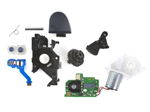
  • Let's take a quick deep dive on these triggers:

  • First up, the button sensors—R1 on the left and R2 on the right. R2 seems to use a "two-stage" sensor to differentiate partial and full trigger pulls, while R1 is a plain-Jane digital switch.

  • Next, the plastic frame, metal pin, and spring. These pieces perform the non-adaptive R2 trigger action, without the rest of the fancy parts.

  • The gear system works together as demonstrated in the previous step: the white worm gear (from the green bullet below) spins the circular gear, which drives the arm up to resist R2's lever action.

  • The white gear housing holds all the gear components together. The silver motor sticking out the bottom drives the worm gear. Its leads are soldered to the trigger module's circuit board (up next).

  • Finally, a circuit board to bring it all together! There are two ribbon cable connections: one to the buttons, and one to the motherboard. The black encoder measures the rotation of the circular gear from the yellow bullet.

Petit approfondissement par rapport au fonctionnement de ces gâchettes :

Tout d'abord les capteurs des boutons : R1 à gauche et R2 à droite. R2 semble utiliser un capteur "à deux phases" pour différencier entre les appuis partiels et complets sur les gâchettes, tandis que R1 est un commutateur numérique lambda.

Ensuite il y a le châssis en plastique, la broche en métal et le ressort. Ces pièces assurent le fonctionnement de la gâchette non adaptative R2 sans le reste des pièces sophistiquées.

Le système d'engrenage fonctionne comme expliqué dans l'étape précédente : l'engrenage à vis blanc (voir la puce verte plus bas) fait tourner l'engrenage circulaire qui, à son tour, fait monter le bras vers le haut pour résister à l'effet de levier du R2.

Le boîtier de l'engrenage blanc rassemble tous les composants de l'engrenage. Le moteur argenté qui dépasse en bas fait tourner l'engrenage à vis. Ses câbles sont soudés au circuit imprimé du module de gâchette (voir prochaine puce).

Et enfin le circuit imprimé pour connecter tout cela ! Il y a deux connexions de nappe : une vers les boutons et une autre vers la carte mère. L'encodeur noir mesure la rotation de l'engrenage circulaire (de la puce jaune).

crwdns2944171:0crwdnd2944171:0crwdnd2944171:0crwdnd2944171:0crwdne2944171:0