crwdns2933423:0crwdne2933423:0

Reemplazo de tarjeta madre en Anycubic Predator BTT SKR

crwdns2936315:0crwdne2936315:0
crwdns2936331:0crwdne2936331:0
crwdns2931653:08crwdne2931653:0
Anycubic Predator BTT SKR 1.4 Motherboard Replacement, Wire Cooling Fans: crwdns2935265:00crwdnd2935265:01crwdnd2935265:03crwdne2935265:0 Anycubic Predator BTT SKR 1.4 Motherboard Replacement, Wire Cooling Fans: crwdns2935265:00crwdnd2935265:02crwdnd2935265:03crwdne2935265:0 Anycubic Predator BTT SKR 1.4 Motherboard Replacement, Wire Cooling Fans: crwdns2935265:00crwdnd2935265:03crwdnd2935265:03crwdne2935265:0
Wire Cooling Fans
  • You have two options here. You can either let the software control the hotend fan, or leave it always on. There are benefits to both, and you can switch later on if you need to.

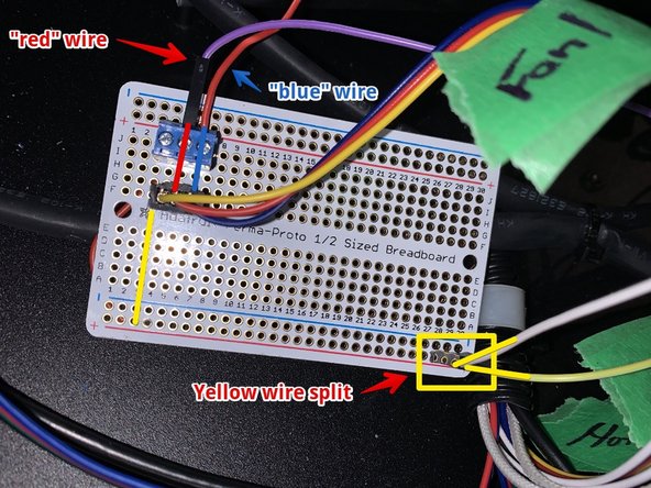
  • You will need to split the yellow wire coming from the FAN1 connector. I have done that using a small protoboard, but you can do that any number of ways.

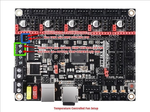
  • To connect the part cooling fan you need to connect one line coming from the yellow FAN1 to the SKR FAN0 connector where marked. The blue FAN1 wire gets connected to the second SKR FAN0 pin. If possible, crimp them into a dupont/JST-SM connector to save yourself later.

  • If you are using the temperature-controlled hotend fan option (my recommendation using the stock hotends), then you connect one yellow FAN1 wire) to the HE1 connector where marked, and the red FAN1 wire to the other HE1 connector where marked.

  • If you are using the always-on hotend fan option (recommended if you're using all-metal heat break and upgraded hotends) then you connect one yellow FAN1 wire to the SKR FAN1 marked area, and connect the red FAN1 wire to the SKR FAN1 marked area.

  • The Anycubic fan system uses a single +24VDC common line (yellow wire on the original FAN1 connector). The GND is not a common GND on the fan plugs, so do not short the GNC lines on the fan plug. Only a single +24VDC is needed to power the fans as it is a common line for all fans.

Tienes dos opciones. Puedes dejar que el software controle el ventilador del hotend o dejarlo siempre encendido. Ambas opciones tienen sus ventajas y puedes activarlas más adelante si lo necesitas.

Deberás dividir el cable amarillo que viene del conector FAN1. Yo lo he hecho con una placa de pruebas pequeña, pero puedes hacerlo de muchas maneras.

Para conectar el ventilador de refrigeración de piezas, debes conectar una línea que viene del FAN1 amarillo al conector SKR FAN0 donde está marcado. El cable azul del FAN1 se conecta al segundo pin del SKR FAN0. Si es posible, engarza los cables en un conector dupont/JST-SM para ahorrarte problemas más adelante.

Si estás usando la opción de ventilador del hotend controlado por temperatura (mi recomendación es usar los hotends de serie), conecta un cable amarillo del FAN1 al conector HE1 donde está marcado y el cable rojo del FAN1 al otro conector HE1 donde está marcado.

Si estás utilizando la opción de ventilador de hotend siempre encendido (recomendado si está utilizando un disyuntor de calor totalmente metálico y hotends mejorados), conecta un cable FAN1 amarillo al área marcada SKR FAN1 y conecta el cable FAN1 rojo al área marcada SKR FAN1.

El sistema de ventiladores Anycubic utiliza una única línea común de +24 V CC (cable amarillo en el conector FAN1 original). La GND no es una GND común en los conectores de los ventiladores, por lo que no cortocircuites las líneas GNC en el conector de los ventiladores.

Solo se necesita una única +24 V CC para alimentar los ventiladores, ya que es una línea común para todos los ventiladores.

crwdns2944171:0crwdnd2944171:0crwdnd2944171:0crwdnd2944171:0crwdne2944171:0