crwdns2931529:0crwdnd2931529:0crwdnd2931529:0crwdnd2931529:03crwdnd2931529:0crwdne2931529:0
crwdns2935425:06crwdne2935425:0


-
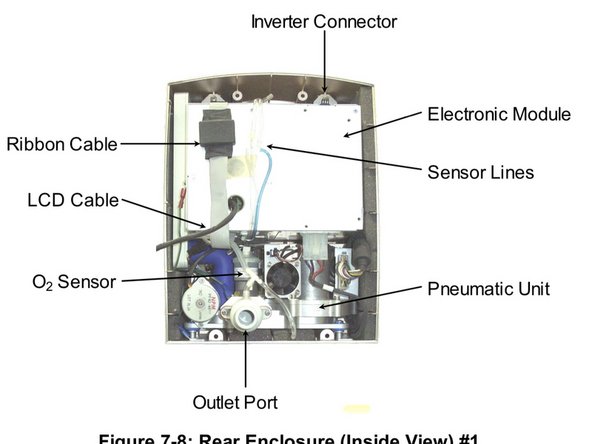
Disconnect the ribbon cable from the interface PC board located in the middle of the front enclosure.
-
Disconnect the green ground wire and receptacle from the pneumatic unit (just above the outlet port).
-
Disconnect the inverter cable from the top of the electronic module.
-
With the LCD cable still tethered, lay the front enclosure, face down, on the protective surface.
-
It is best to orient the front enclosure so that it is facing you, upside down with the tethered LCD cable towards the right
-
Detach the green LCD cable ground wire from the LCD shield by removing the (1) 3mm x 14mm Phillips head screw and lock washer located in the corner near the LCD connector.
-
Use the nutdriver to remove the (2) 4mm lock nuts from the LCD connector location on the front enclosure. Remove the aluminum U-shaped bracket from the LCD connector site and pull out the LCD connector and cable.
-
Remove the aluminum U-shaped bracket from the LCD connector site and pull out the LCD connector and cable.
crwdns2944171:0crwdnd2944171:0crwdnd2944171:0crwdnd2944171:0crwdne2944171:0