crwdns2915892:0crwdne2915892:0
Battery not lasting long? Swap it out (requires soldering).
crwdns2942213:0crwdne2942213:0
-
-
To aid in visualization, the two clips boxed in red are located closest to the headphone jack.
-
-
-
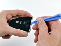
Insert the large iPod opening tool into the seam between the front case and rear panel of the iPod, above the dock connector. The tool's edge should point toward the rear panel to prevent any accidental scratching of the anodized aluminum front case.
-
-
-
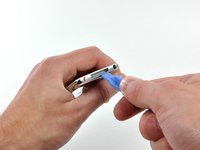
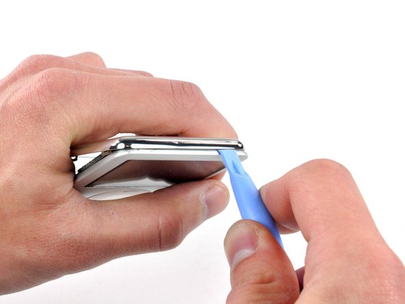
Insert a small iPod opening tool into the seam on the headphone jack side of the Nano, with the edge of the tool pointing toward the rear panel.
-
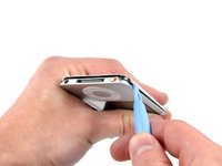
Gently enlarge the existing gap by pressing/wiggling the small iPod opening tool into the gap near each of the the two tabs attached to the rear case, pushing the clips toward the center of the Nano until both have been freed.
-
-
-
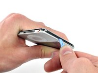
Repeat the same procedure listed in the previous step to free the three clips along the hold switch side of the Nano.
-
-
-
Insert an iPod opening tool into the gap near the top left corner of the Nano and work to free the three clips along the top edge of the rear panel.
-
After ensuring all tabs are free, separate the two halves of the iPod.
-
The rear panel is now free from the iPod.
-
-
-
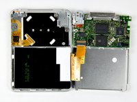
With the rear case removed, the back side of your Nano should now look like this.
-
-
-
-
Remove the following six screws:
-
One 1.8 mm Phillips.
-
Three 1.9 mm Phillips.
-
One 2.4 mm Phillips.
-
One 2.6 mm Phillips.
-
-
-
Using a spudger, flip up the brown click wheel ribbon cable retaining clip.
-
-
-
Use the tip of a spudger to slide the click wheel ribbon cable out of its socket.
-
-
-
Lift the logic board assembly out of the front case from the click wheel connector side (the cable you just disconnected). Rotate the logic board assembly about the display ribbon cable and lay it next to the front case.
-
-
-
Use a spudger to flip up the display ribbon cable retaining clip.
-
-
-
Slide the display ribbon cable out of its socket.
-
-
-
Before proceeding, remove the metal EMI finger shown by pulling it away from the adhesive on the logic board.
-
-
-
Before de-soldering the battery cables, you must remove a small amount of black rubbery adhesive securing them to the logic board.
-
-
-
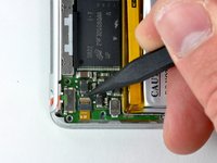
Push the tip of a spudger beneath the rubber adhesive and toward the battery to free it from the surface of the logic board.
-
Start freeing the adhesive from around one of the outer leads, then free it from the two gaps between leads, and finally push the spudger along the back side of the leads to completely remove it from the logic board/battery leads.
-
-
-
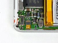
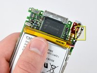
The battery leads, now free of adhesive, should look like this.
-
-
crwdns2935267:0crwdne2935267:0Tweezers$4.99
-
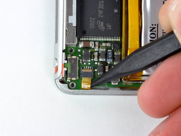
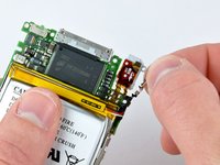
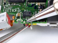
Begin by heating the exposed end of the white battery lead with the tip of a soldering iron while simultaneously pulling the lead away from the connection, using tweezers to grasp the lead by the insulation.
-
-
-
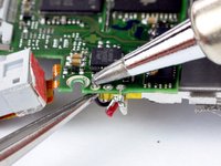
De-solder the remaining leads, following the procedure illustrated in the previous step.
-
-
-
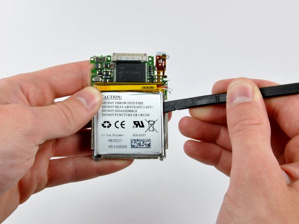
All leads should now be de-soldered and disconnected from the logic board.
-
-
-
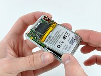
Using a spudger, pry the battery up from the adhesive holding it to the battery shield.
-
Start prying at the upper right corner of the battery and work your way around the perimeter until the battery has lifted enough to grab it with your fingers.
-
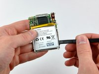
Remove the battery from the battery shield.
-


To reassemble your device, follow these instructions in reverse order.
To reassemble your device, follow these instructions in reverse order.
