crwdns2915892:0crwdne2915892:0
Prereq-only guide for detaching the display assembly en route to other repairs.
crwdns2942213:0crwdne2942213:0
-
-
Use a spudger or a fingernail to disconnect the two lower display connectors by prying them straight up from their sockets on the logic board.
-
-
-
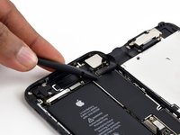
Remove the two 1.3 mm Phillips #000 screws securing the bracket over the front panel sensor assembly connector.
-
-
-
-
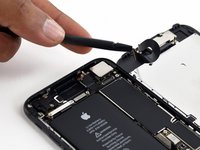
Disconnect the front panel sensor assembly connector from its socket on the logic board.
-


To reassemble your device, follow these instructions in reverse order.
To reassemble your device, follow these instructions in reverse order.
crwdns2935221:0crwdne2935221:0
crwdns2935229:04crwdne2935229:0
