crwdns2915892:0crwdne2915892:0
Use this guide to replace a scratched or damaged rear case on your iPhone 5c.
This guide requires removing the battery. The adhesive strips securing the battery are not re-usable, so you'll want to have a supply of replacement adhesive strips on hand before you begin. Alternatively, you can secure the battery using a piece of double-sided tape. The battery is pretty tightly secured in the device, but the tape will keep it from rattling.
You can also use this guide for reference when replacing the power button grounding cable.
crwdns2942213:0crwdne2942213:0
-
-
If your display glass is cracked, keep further breakage contained and prevent bodily harm during your repair by taping the glass.
-
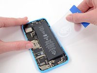
Lay overlapping strips of clear packing tape over the iPhone's display until the whole face is covered.
-
-
-
Power off your iPhone before beginning disassembly.
-
Remove the two 3.8 mm P2 Pentalobe screws on either side of the Lightning connector.
-
-
crwdns2935267:0crwdne2935267:0iSclack$24.99
-
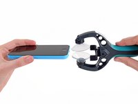
Close the handle on the iSclack, opening the suction-cup jaws.
-
Place the bottom of your iPhone in between the suction cups, against the plastic depth gauge.
-
The top suction cup should rest just above the home button.
-
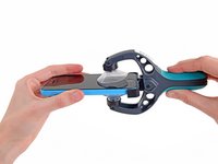
Open the handles to close the jaws of the iSclack. Center the suction cups and press them firmly onto the top and bottom of the iPhone.
-
-
-
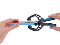
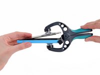
Hold onto your iPhone securely and close the handle of the iSclack to separate the suction cups, pulling the front panel up from the rear case.
-
The iSclack is designed to safely open your iPhone just enough to separate the pieces, but not enough to damage any cables.
-
Skip the next three steps and continue on to Step 8.
-
-
-
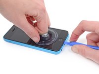
Press a suction cup onto the screen, just above the home button.
-
-
-
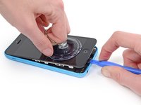
While holding the iPhone down with one hand, pull up on the suction cup to slightly separate the front panel assembly from the rear case.
-
With a plastic opening tool, begin to gently pry the rear case down, away from the display assembly, while you pull up with the suction cup.
-
-
-
Pull the plastic nub to release the vacuum seal on the suction cup.
-
Remove the suction cup from the display assembly.
-
-
-
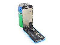
Lift the home button end of the front panel up to gain access to the connectors near the top of the phone.
-
Open the display to about a 90º angle, and lean it against something to keep it propped up while you're working on the phone.
-
In a pinch, you can use an unopened canned beverage to hold the display.
-
Add a rubber band to keep the display securely in place while you work. This prevents undue strain on the display cables.
-
-
-
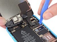
Remove the two 1.6 mm Phillips #000 screws securing the metal battery connector bracket to the logic board.
-
-
-
Remove the metal battery connector bracket from the iPhone.
-
-
-
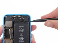
Use a spudger or a clean fingernail to gently pry the battery connector up from its socket on the logic board.
-
-
-
Remove the following Phillips #000 screws securing the front panel assembly cable bracket to the logic board:
-
Two 1.3 mm screws
-
One 1.7 mm screw
-
One 3.25 mm screw
-
-
-
Remove the front panel assembly cable bracket from the logic board.
-
-
-
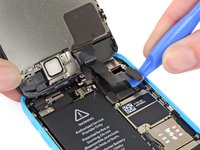
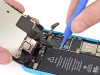
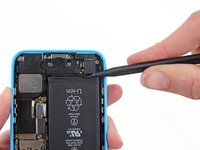
Use a plastic opening tool or a fingernail to disconnect the front-facing camera and sensor cable connector.
-
-
-
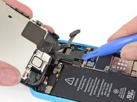
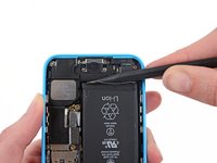
Use a plastic opening tool or a fingernail to disconnect the LCD cable connector.
-
-
-
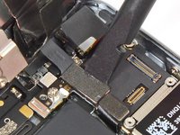
Remove the front panel assembly from the rear case.
-
-
-
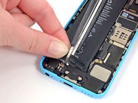
Insert a SIM card eject tool or a paperclip into the small hole in the SIM card tray.
-
Press the SIM card eject tool inwards to eject the tray.
-
This may require a significant amount of force.
-
-
-
Remove the SIM Card tray assembly from the iPhone.
-
-
-
Remove the 2.0 mm Phillips #000 screw securing the SIM ejector.
-
-
crwdns2935267:0crwdne2935267:0Tweezers$4.99
-
Use a set of tweezers to remove the SIM ejector from the phone.
-
-
-
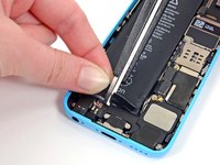
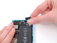
Run the tip of a spudger between the battery and the headphone jack to unfold the battery adhesive tab.
-
-
-
Pull the battery adhesive tab away from the phone.
-
-
-
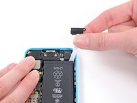
Cut the black battery adhesive tab between the two white adhesive strips, separating them.
-
-
-
-
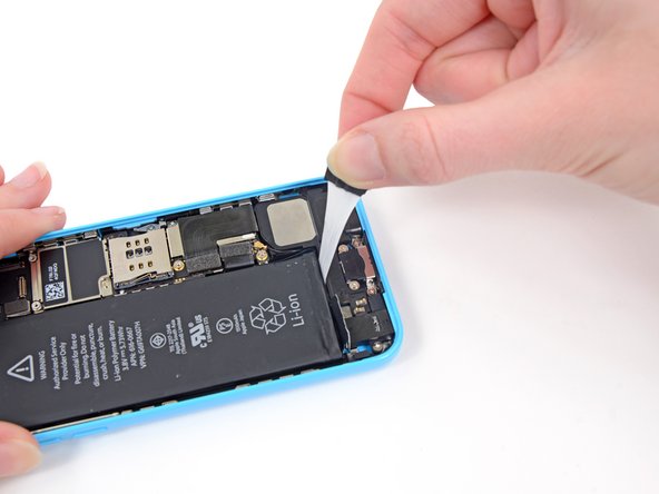
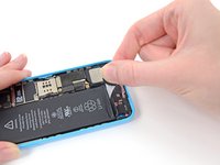
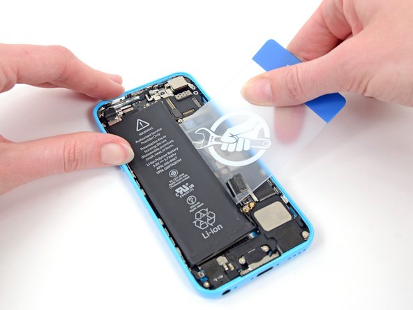
Slowly pull one of the battery adhesive strips away from the battery, toward the bottom of the iPhone.
-
Pull steadily, maintaining constant tension on the strip as it slips out from between the battery and the rear case. For best results, pull the strip at a 60º angle or less.
-
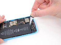
Guide the strip carefully around the corner and up the side of the battery. Be careful not to snag it on any of the other internal iPhone components.
-
-
crwdns2935267:0crwdne2935267:0Tweezers$4.99
-
Remove the battery from your iPhone.
-
-
crwdns2935267:0crwdne2935267:0Plastic Cards$2.99
-
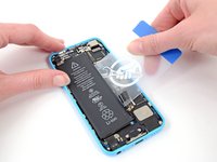
Apply a few drops of isopropyl alcohol (90% or greater) under the battery and let it flow around the adhesive to help weaken it. High concentration isopropyl alcohol acts as a solvent and dries without leaving any residue, so it will not hurt your iPhone.
-
Carefully wedge a plastic card under the battery on the side nearest the logic board.
-
Slide the card from the top of the battery to the bottom, pushing toward the edge of the case.
-
-
-
If the battery is still stuck to the case, follow our iOpener heating instructions or use a hair dryer to heat the adhesive securing your battery to the rear case.
-
Lay the iOpener flat on the backside of the iPhone to the right of the camera. Smooth it out so that there is good contact between the back of the iPhone and the iOpener.
-
Let the bag sit on the iPhone for approximately 90 seconds before attempting to remove the battery.
-
If using a hair dryer or heat gun, heat the back of the iPhone until it's slightly too hot to touch.
-
-
-
Lift and remove the battery from the iPhone.
-
Adhere the battery, disconnect it, and continue reassembling your device.
-
-
-
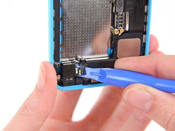
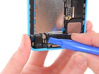
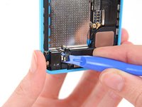
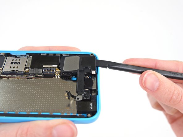
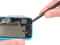
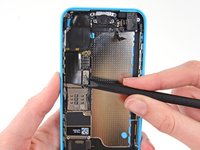
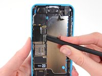
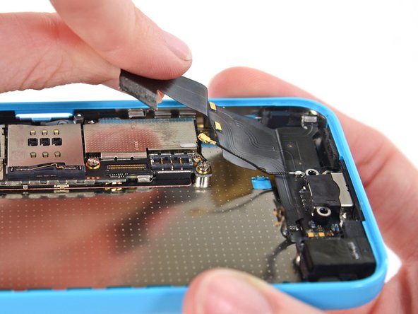
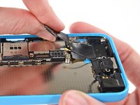
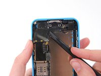
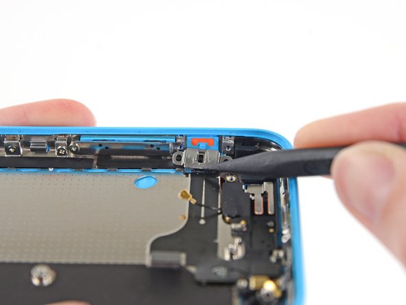
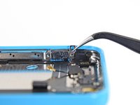
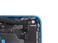
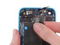
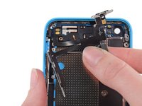
Use a plastic opening tool to peel the home button spring contact cable up from the speaker enclosure.
-
-
-
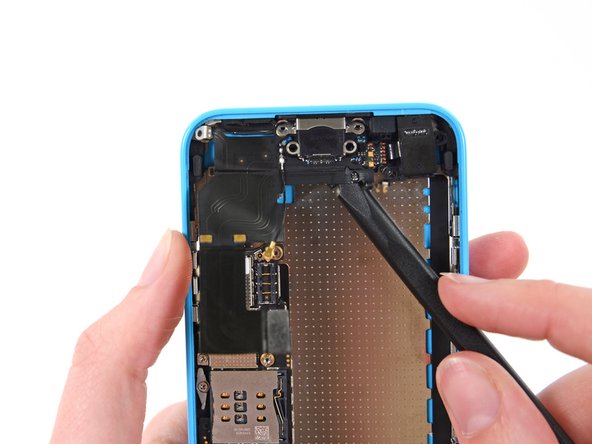
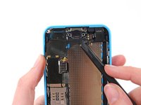
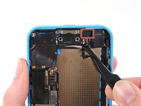
Remove the following screws securing the speaker enclosure to the rear case:
-
Two 2.7 mm Phillips #000 screws
-
One 2.2 mm Phillips #000 screw
-
-
-
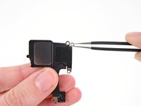
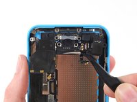
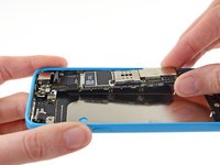
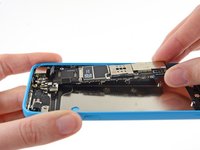
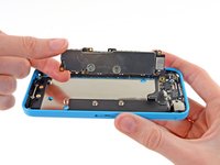
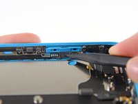
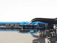
Use the flat end of a spudger to gently pry the speaker enclosure up from the rear case.
-
-
-
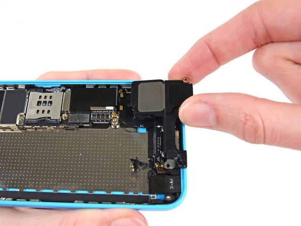
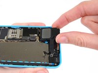
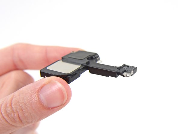
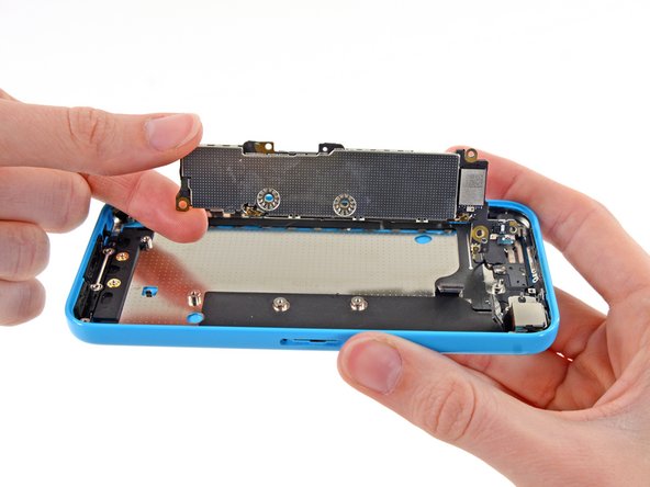
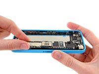
Remove the speaker enclosure. Be careful not to snag it on the antenna cable.
-
-
-
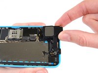
Use a plastic opening tool to disconnect the Lightning connector ribbon cable from its socket on the logic board.
-
-
-
The Lightning connector cable is lightly adhered to a shield on the logic board. Use the flat end of a spudger to gently peel the cable up.
-
-
-
Disconnect the cellular antenna connector from the base of the logic board.
-
-
-
Remove the following screws securing the Lightning connector to the rear case:
-
Two 3.4 mm Phillips #000 screws
-
One 2.2 mm Phillips #000 screw
-
One 2.7 mm Phillips #000 screw
-
-
-
Gently peel the Lightning connector assembly up from the rear case.
-
-
-
You may need to use the flat end of a spudger to completely free the assembly.
-
-
-
Remove the Lightning connector assembly.
-
There is a small rubber gasket attached to the microphone. Be sure to transfer it to the new assembly.
-
-
-
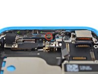
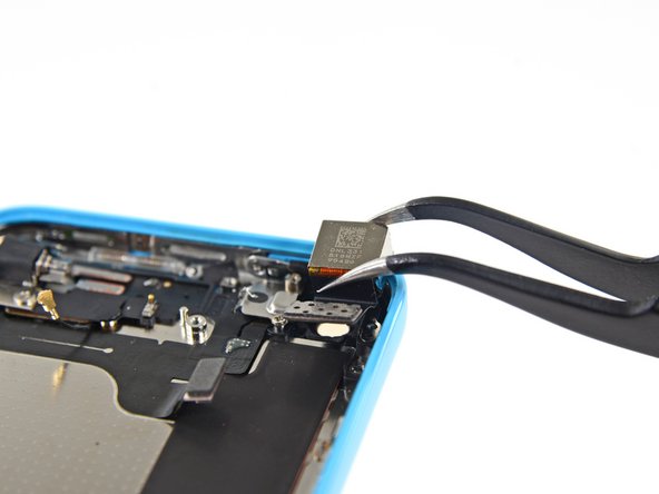
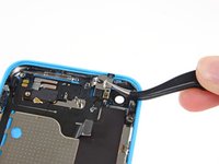
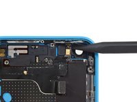
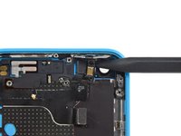
Use the flat end of a spudger to disconnect the audio control cable connector from its socket on the logic board.
-
Disconnect the rear facing camera cable connector from its socket on the logic board.
-
-
crwdns2935267:0crwdne2935267:0Tweezers$4.99
-
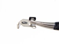
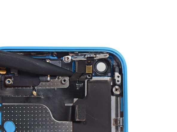
A small piece of tape may obscure the logic board grounding clip. If so, use a pair of tweezers to remove the tape.
-
-
-
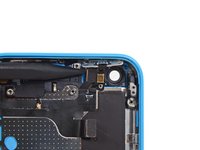
Remove the following screws securing the logic board grounding clip to the rear case:
-
1.2 mm Phillips #000 in the top side-wall
-
2.5 mm Phillips #000
-
-
-
Use tweezers to remove the logic board grounding clip.
-
-
crwdns2935267:0crwdne2935267:0Standoff Screwdriver for iPhones$5.49
-
Remove the following screws securing the logic board to the rear case:
-
Two 2.3 mm Phillips screws
-
Three 2.7 mm standoff screws
-
-
-
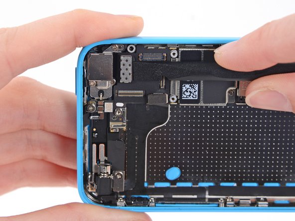
Holding the phone level, lift the bottom end of the logic board up enough to grasp it with your fingers.
-
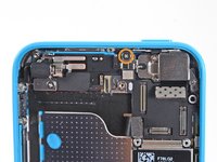
Pull the logic board away from the rear-facing camera just enough to expose the gold contact cap under the top end of the board.
-
Remove the gold-colored contact cap from the threaded post in the rear case, and set it aside.
-
-
-
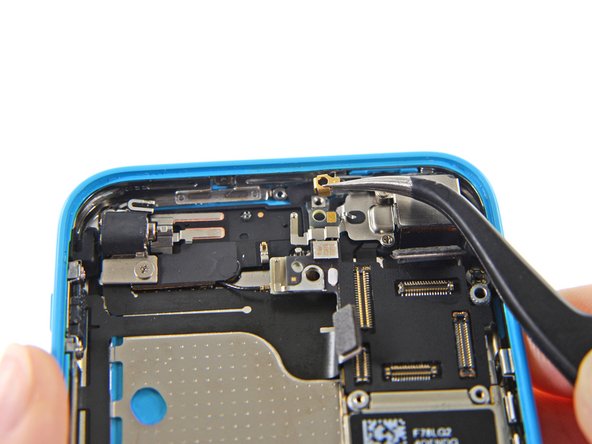
Flip the logic board up toward the volume control buttons to expose the antenna connector.
-
-
-
Disconnect the antenna connector from the back of the logic board.
-
-
-
Remove the logic board from the rear case.
-
-
-
Remove the two 1.5 mm Phillips #000 screws securing the rear camera cover to the rear case.
-
-
-
Remove the rear facing camera cover.
-
-
-
Remove the following screws securing the vibrator motor to the rear case:
-
1.2 mm Phillips #000
-
2.2 mm Phillips #000
-
-
-
Remove the following screws securing the upper assembly contact bracket to the rear case:
-
3.0 mm standoff screw
-
1.5 mm Phillips #000 screw
-
-
-
Remove the upper assembly contact bracket from the rear case.
-
A small rubber bumper may fall off the top of the bracket—take care not to lose it.
-
-
-
Remove any foam tape obscuring the screws near the camera cavity.
-
-
-
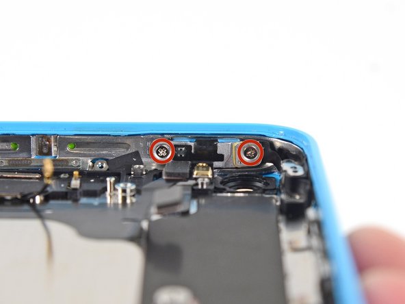
Remove the two 1.4 mm Phillips #000 screws securing the power/sleep button bracket.
-
-
crwdns2935267:0crwdne2935267:0Tweezers$4.99
-
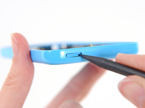
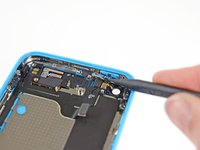
Use the pointed end of a spudger to gently fold the power/sleep button bracket down from the top of the rear case.
-
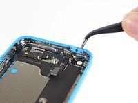
Use tweezers to grab and remove the button.
-
-
-
Remove the two 1.6 mm Phillips #000 screws from the mute/silent switch bracket.
-
-
-
Remove this mute/silent switch bracket clip and set it aside.
-
Use the tip of a spudger to flip the mute/silent switch bracket down.
-
-
-
Use tweezers to remove the mute/silent switch.
-
-
-
Remove the 1.6 mm Phillips #000 screw securing the volume rocker bracket to the side wall.
-
-
-
Use the tip of a spudger to fold the volume rocker bracket down from the side wall. Remove the volume rocker.
-
-
-
Use the tip of a spudger to peel the power/sleep button cable off of the rear case.
-
-
-
Run a spudger gently under the flash assembly cable to separate it from the phone.
-
-
-
Peel the upper assembly cable up from right to left to separate the adhesive holding it to the case.
-


To reassemble your device, follow these instructions in reverse order.
To reassemble your device, follow these instructions in reverse order.
crwdns2935221:0crwdne2935221:0
crwdns2935229:045crwdne2935229:0

crwdns2947412:03crwdne2947412:0
crucial information is missing:
when removing the lightning connector module, not only the black "rubber gasket" attached to the microphone needs to be carefully transfered to the new rear case, but also
-the rectangular black plastic microphone filter with the small cylindrical extrusion, which is stuck to the case
-the grid/foam frame protecting the speaker, which is also glued to the case
-the 2 gold connector rings around the screw holes on the upper black plastic part at the bottom of the case.
-the metal piece remotely similar to a "bone" shape, two rings connected by a longer part, stuck to the lower black plastic part at the bottom of the case.
-in general the 4 metal parts screwed to the side of the case, functioning as snap-locks for the front display. (3x with 2 snap lock elements, 1x with only 1, next to the volume rocker
-the black ring round the hole where the wifi/bluetooth antenna goes, underneath the vibration motor.
depending on the case you're getting, all of these need to be transfered.
Also the transfer of the WiFi/Bluetooth antenna is completely missing. In my case the antenna to logic board connector cable broke, so i had to replace it
David -
where is this located Apple Part Number: 821-1769
I replaced old back body with the new one and when I finished this part was still on my desk and gps doesn't get signal anymore :)