crwdns2915892:0crwdne2915892:0
The plastic rear half of the iPhone.
crwdns2942213:0crwdne2942213:0
-
-
If your display glass is cracked, keep further breakage contained and prevent bodily harm during your repair by taping the glass.
-
Lay overlapping strips of clear packing tape over the iPhone's display until the whole face is covered.
 crwdns2952109:0crwdne2952109:0
-
-
-
Remove the two 3.7mm Phillips #00 screws from the dock-connector end of the iPhone.
-
-
-
Remove the metal handle from the suction cup. It's easier and safer to grip the suction cup's base instead of the metal handle.
-
Use a small suction cup near the Home button to gently pull up the bottom portion of the iPhone's display assembly.
-
-
-
Rotate the display assembly up until it is at an angle of approximately 45 degrees.
-
-
-
Continue to hold the display assembly with one hand, and use your other hand and a spudger to disconnect the black ribbon cable labeled "1". (Cable 1 is for the display)
-
-
-
Rotate the display assembly up until it is roughly vertical. This will allow easier access for disconnecting the remaining cables.
-
Use a spudger to disconnect the black ribbon cable labeled "2". (Cable 2 is for the capacitative touch panel)
-
-
-
Use a spudger to flip up the white plastic tab holding the ribbon cable "3" in place. The white tab will rotate up 90 degrees, releasing the ribbon cable.
-
Slide the black ribbon cable out of its connector, and remove the display assembly from the iPhone.
-
-
-
Insert your SIM eject tool or a paper clip into the hole next to the headphone jack.
-
Press down on the tool until the SIM card tray pops out.
-
Grasp the SIM card tray and slide it out of the iPhone.
-
-
-
Use a spudger to disconnect the ribbon cable labeled "4."
-
-
-
Use a spudger to disconnect the ribbon cable labeled "5."
-
-
-
-
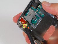
Use a spudger to disconnect the ribbon cable labeled "6."
-
-
-
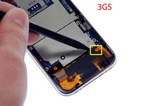
Remove the following 8 screws:
-
Five 2.3 mm Phillips #00 screws with partial threads securing the logic board to the rear case.
-
Two 2.3 mm Phillips #00 screws with full threads securing the logic board and camera.
-
One 2.9 mm Phillips #00 screw from beneath the "Do not remove" sticker.
-
Note for re-assembly:
-
The screw that goes next to the camera (bottom right orange highlighted screw) also has a metal strip that holds the camera in place.
-
-
-
Use a spudger to gently pry the camera up and out of its housing in the rear case.
-
-
-
Use a spudger to gently pry up the end of the logic board closest to the dock connector.
-
-
-
Slide the logic board towards the dock connector and out of the iPhone.
-
When replacing the logic board after installing battery, connect the camera to the logic board before inserting it into the case. Then make sure to set the top section of the logic board (where the SIM tray is) in place before settling the rest of the board in place. This is important, as sometimes the SIM card slot will not align into place. Once the top section is in place, the bottom section can be maneuvered into place. You will know the logic board is correctly installed when the SIM tray is aligned with the opening in the iPhone case and the camera module seats neatly into its place.
-
-
-
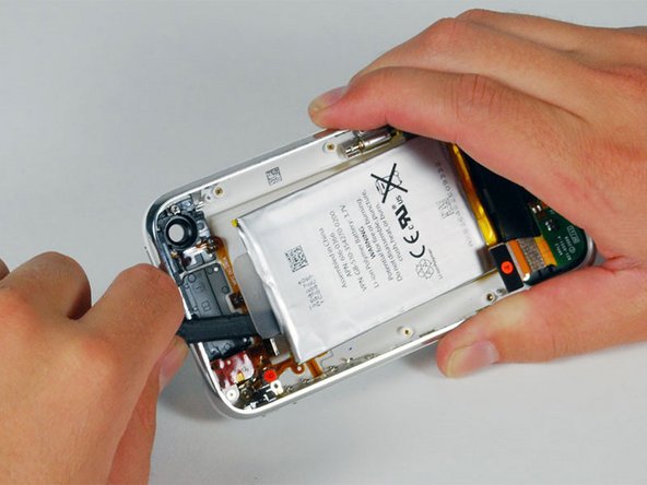
Use a spudger to pry the battery up from the rear case. The battery is attached with an adhesive strip around the perimeter of the battery.
-
-
-
Remove the two Phillips #00 screws securing the on/off switch to the front bezel.
-
-
-
Carefully peel up the orange ribbon cable from the rear case.
-
-
-
Remove the following 4 screws:
-
Three 1.8 mm Phillips #00 screws securing the headphone jack and GPS antenna to the rear case. Note the order in which you remove the screws, as the left one has a slightly larger head.
-
One 3.8 mm Phillips #00 screw in the plastic loop near the headphone jack.
-
-
-
Remove the four Phillips #00 screws securing the volume and mute switch.
-
The mute switch assembly screws should be tightened with the switch in the off position. Check the protrusion of the switch when turned on, since it may not stick out far enough to operate if the switch assembly is incorrectly positioned. (Check the gap between the switch frame and the bezel (white gap showing between the two screws near the 6). The screw on the far right is slightly longer than the other 3 screws. When reassembling the phone, keep this in mind.
-
-
-
Carefully lift the headphone jack assembly out of the iPhone.
-
Switch the green mute switch down (towards the back side of the iPhone) into mute position. This will make it much easier to insert it, once the new mute button is in place.
-
-
-
Remove the single 2.4mm Phillips #00 screw securing the black plastic spacer.
-
-
-
Use a spudger to pry up the black plastic antenna housing from the rear panel.
-
Lift the black plastic GPS antenna housing out of the iPhone.
-
-
-
Remove the on/off switch button from the iPhone.
-
-
-
Remove the mute button from the iPhone.
-
-
-
Remove the two 1.9mm Phillips #00 screws securing the vibrator to the rear case.
-
Lift the vibrator up and out of the iPhone.
-
Keep these screws separate from the others as these have a smaller diameter than the others.
-
-
-
Remove the following 3 screws:
-
Two 1.5 mm Phillips #00 screws, one on either side of the dock connector.
-
One 2.4 mm Phillips #00 screw near the ribbon cable labeled "4."
-
-
-
Lift the dock connector assembly up and out of the iPhone.
-
-
-
The rear case and attached front bezel remain.
-


To reassemble your device, follow these instructions in reverse order.
crwdns2935221:0crwdne2935221:0
crwdns2935229:0227crwdne2935229:0

crwdns2947412:011crwdne2947412:0
After completely disassembling the phone, I have a leftover small piece (~1cm long) of metal with a screw hole. I cannot for the life of me figure out where this small metal piece goes. Does it have anything to do with the black strip visible still left attached to the rear panel in Step 30?
Charlie
Charles Arias - crwdns2934203:0crwdne2934203:0 crwdns2950251:0crwdne2950251:0
Hi Charles!
I have the same problem! cannot figure out where the 1 cm part with a screw hole goes. have you figured out yet?
kuria - crwdns2934203:0crwdne2934203:0 crwdns2950251:0crwdne2950251:0
That part could be the spring that tensions the camera into it's housing, you should see if you can fit it into the small slot in the camera, if so that's your piece.
Logan - crwdns2934203:0crwdne2934203:0 crwdns2950251:0crwdne2950251:0
Help! When I gently pulled on the suction cup to open up the phone the glass screen came away, not the whole front assembly. It looks like it was badly glued down (previous (paid!) repair). How do I now get the front assembly up?
Alice Elmhirst - crwdns2934203:0crwdne2934203:0 crwdns2950251:0crwdne2950251:0
When I gently pulled on the suction cup the front glass came away from the bezel. This seems to be the result of a previous bad repair job. Now I wonder how to pull up the front assembly???
Alice Elmhirst - crwdns2934203:0crwdne2934203:0 crwdns2950251:0crwdne2950251:0