crwdns2915892:0crwdne2915892:0
Use this guide to replace the logic board.
crwdns2942213:0crwdne2942213:0
-
crwdns2935267:0crwdne2935267:0Tweezers$4.99
-
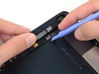
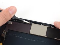
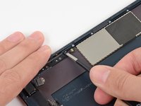
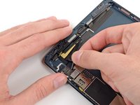
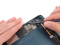
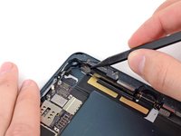
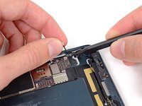
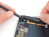
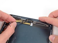
Use tweezers to peel up and remove the small piece of tape covering the front-facing camera cable connector.
-
-
-
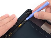
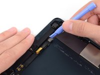
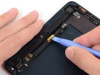
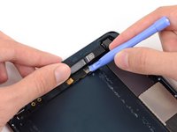
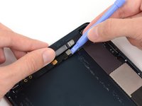
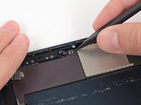
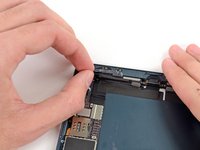
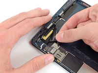
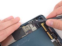
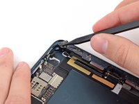
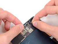
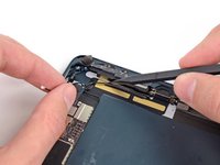
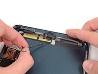
Use a plastic opening tool to gently pry the lower metal plate up from the front-facing camera cable connector.
-
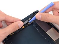
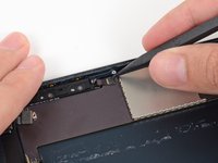
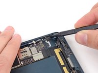
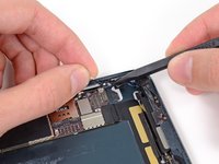
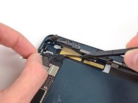
Being careful not to break the plate or the tape attached to it, pry it up and fold it away from the front-facing camera cable connector.
-
-
-
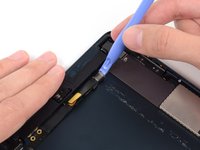
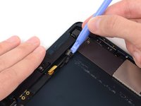
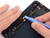
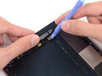
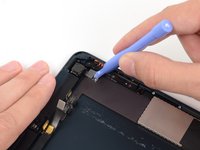
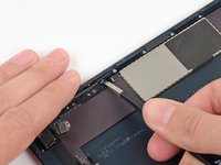
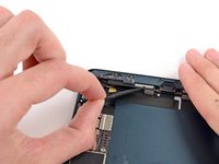
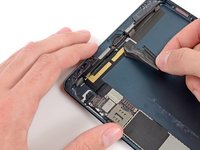
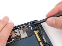
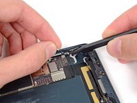
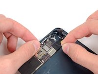
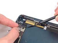
Gently pry the second (upper) metal plate up from the front-facing camera cable connector.
-
Again, carefully pry the plate up and away from the front-facing camera cable connector.
-
-
-
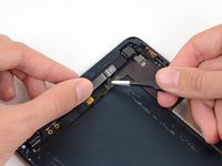
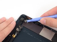
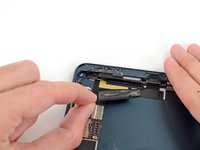
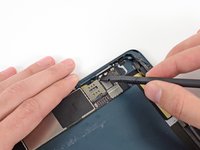
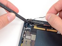
Use a plastic opening tool to pry the front-facing camera cable's connector up from its socket on the logic board.
-
-
-
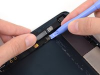
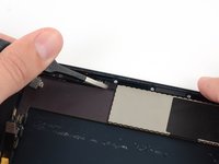
Gently fold the front-facing camera cable up and out of the way of the logic board.
-
-
-
Use tweezers to peel up and remove the small piece of tape covering the headphone jack cable connector.
-
-
-
Use a plastic opening tool to gently pry the lower metal plate up from the headphone jack cable connector.
-
Being careful not to break the plate or the tape attached to it, pry it up and fold it away from the headphone jack cable connector.
-
-
-
Pry the second (upper) metal plate up from the front-facing camera cable connector.
-
Again, carefully pry the plate up and away from the headphone jack cable connector.
-
-
-
-
Use a plastic opening tool to pry the headphone jack cable's connector up out of its socket on the logic board.
-
-
-
Use a plastic opening tool to pry the rear-facing camera cable up from its socket on the logic board.
-
-
-
Use tweezers to peel up and remove the small piece of tape covering the button ribbon cable ZIF connector.
-
-
-
Use the tip of a spudger to lift up the tab on the button ribbon cable ZIF connector.
-
-
-
Use tweezers to pull the button ribbon cable straight out of its ZIF socket on the logic board.
-
-
-
Gently peel back the wide piece of tape covering the top of the right speaker.
-
-
-
Continue peeling the tape, and remove it from the iPad.
-
-
-
Use the flat end of a spudger to disconnect the two bottom antenna cable connectors from their sockets on the logic board.
-
-
-
Use the tip of a spudger to peel back the small piece of tape covering both antenna cables on the bottom right side of the iPad.
-
-
-
With the tip of a spudger, peel up the larger piece of tape covering both antenna cables near the bottom of the rear case.
-
-
-
Use the tip of a spudger to pry the small metal retaining clip off the left antenna cable, then de-route the cable from the clip.
-
-
-
De-route the antenna cable from the corner of the iPad.
-
-
-
Use the tip of a spudger to remove the small piece of tape securing the antenna cable in the bottom right corner of the iPad.
-
-
-
Peel the cable back from the corner of the iPad.
-
-
-
Use the tip of a spudger to pry the antenna cable tape up from the rear case of the iPad.
-
Gently pull the antenna cable out of the way as you work along the piece of tape, to keep it from resealing.
-
-
-
Pull the antenna cable from the slot behind the Lightning connector.
-


To reassemble your device, follow these instructions in reverse order.
To reassemble your device, follow these instructions in reverse order.
