crwdns2915892:0crwdne2915892:0
prerequisite for logic board, heat sink, and CPU
crwdns2942213:0crwdne2942213:0
-
-
Remove the four 7.5 mm T8 screws from behind the GPU on the logic board.
-
-
-
Remove the bracket from behind the GPU heat sink.
-
-
-
-
Remove four black stickers from the back of the CPU heat sink.
-
-
-
Remove four 12.3 mm T10 screws from the back of the CPU heat sink.
-
-
-
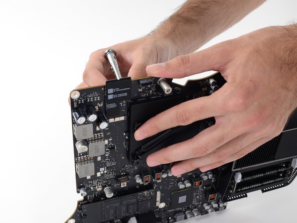
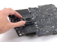
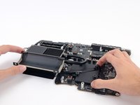
Remove the spring plate from behind the CPU heat sink.
-
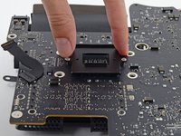
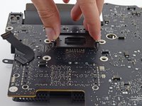
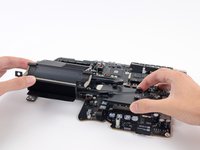
Lift and remove the backing plate from behind the CPU heat sink. The backing plate has two posts that fit into alignment holes in the logic board.
-
-
-
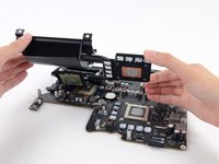
Lift the heat sink up from the logic board.
-


crwdns2935219:0crwdne2935219:0
To reassemble your device, follow these instructions in reverse order.
crwdns2915888:0crwdne2915888:0
To reassemble your device, follow these instructions in reverse order.
