crwdns2915892:0crwdne2915892:0
Use this guide to replace a faulty logic board.
When reassembling your iMac, follow our thermal paste application guide to reapply the thermal paste.
crwdns2942213:0crwdne2942213:0
-
crwdns2935267:0crwdne2935267:0iMac Intel 21.5" Cardboard Service Wedge$4.99
-
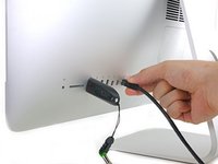
Before beginning any work on your iMac: Unplug the computer and press and hold the power button for ten seconds to discharge the power supply's capacitors.
-
-
-
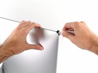
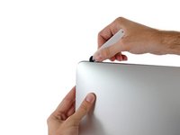
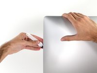
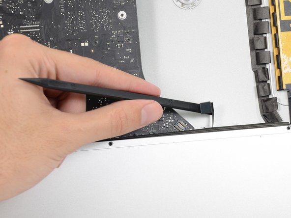
Starting on the left of the display, near the power button, insert the iMac Opening Tool into the gap between the glass panel and the rear enclosure.
-
-
-
Use the tool like a pizza cutter—roll it along through the gap, and it will cut the foam adhesive through the center.
-
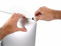
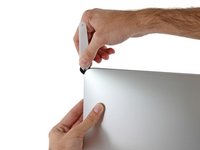
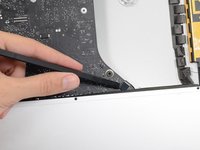
Run the tool up along the left side of the display.
-
-
-
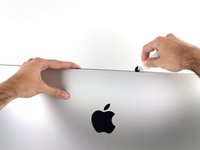
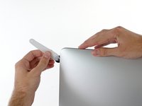
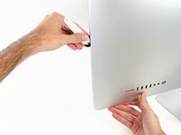
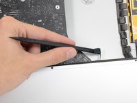
Continue running the tool up around the top left corner.
-
-
-
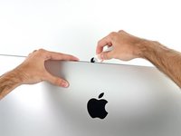
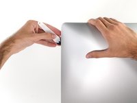
Cut the adhesive along the top left of the display.
-
-
-
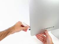
Continue along the top of the display.
-
-
-
Push the tool around the top right corner of the display.
-
-
-
Wheel the tool down along the right side of the display.
-
-
-
Finish pushing the opening tool to the bottom of the right side of the display.
-
-
crwdns2935267:0crwdne2935267:0Plastic Cards$2.99
-
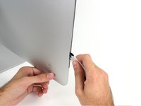
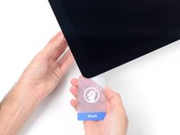
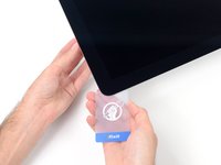
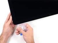
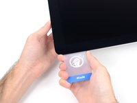
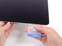
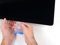
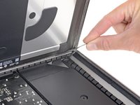
Starting from the top right corner of the iMac, wedge a plastic card between the display and frame.
-
-
-
Gently twist the plastic card sideways to create a gap between the display and frame.
-
Move slowly and be careful not to stress the display glass too much—you only need to make a gap of about 1/4".
-
-
-
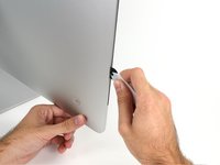
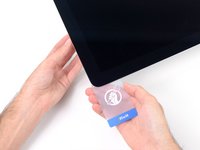
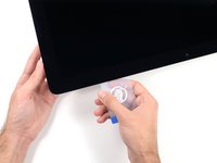
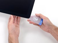
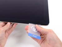
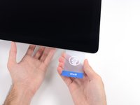
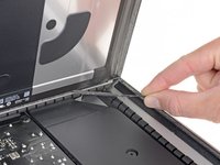
Slide the card toward the center of the display to cut any of the remaining adhesive along the top right corner of the iMac.
-
-
-
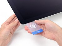
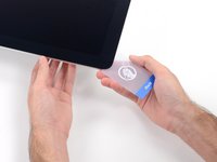
Wedge the plastic card into the top right corner once again, and leave it there to prevent the adhesive from resticking.
-
-
-
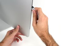
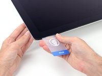
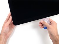
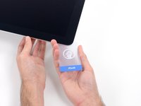
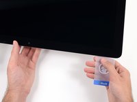
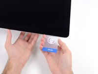
Insert a second plastic card into the gap between the display and frame near the top left corner of the iMac.
-
-
-
Gently twist the card upward, slightly increasing the space between the display and frame.
-
-
-
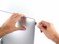
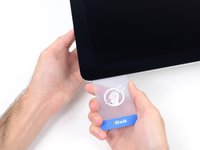
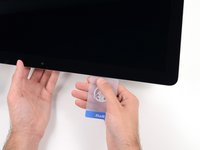
Slide the plastic card toward the center, again stopping just before the iSight camera.
-
-
-
Wedge the plastic card back into the top left corner.
-
-
-
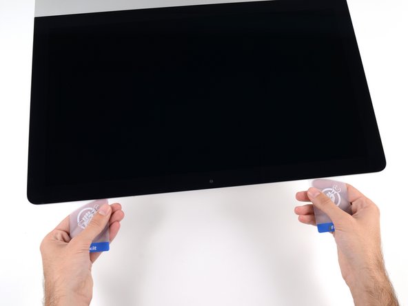
With both plastic cards inserted as shown near the corners, gently twist the cards sideways to increase the gap between display and case.
-
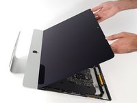
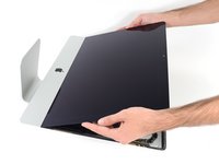
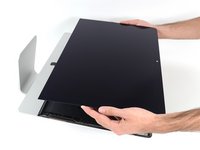
Begin to lift the top of the display up from the frame.
-
-
-
While holding the display up with one hand, use the other hand to unplug the display power cable.
-
-
-
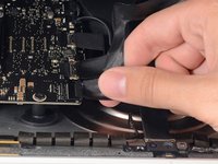
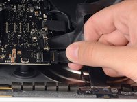
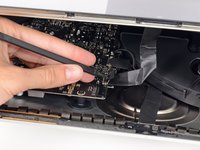
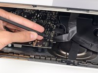
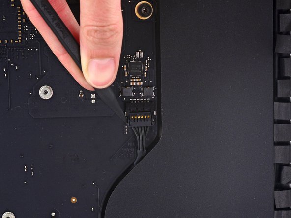
Use the tip of a spudger to flip up the metal retaining bracket on the display data cable.
-
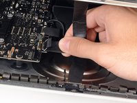
Carefully pull the display data cable from its socket on the logic board.
-
-
-
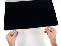
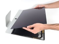
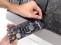
Lift the display up to a near-vertical position.
-
-
crwdns2935267:0crwdne2935267:0Plastic Cards$2.99
-
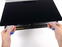
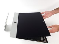
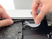
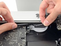
Grasp the small tab at the end of one of the bottom edge display adhesive strips and pull the adhesive toward the top of the iMac to remove it.
-
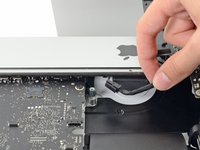
Repeat this step with the other adhesive strip and remove it.
-
-
-
-
Lift the display up from the frame and remove it from the iMac.
-
It may be necessary to slowly lift from one side, to peel against the remaining adhesive.
-
-
-
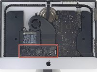
Remove the following five Phillips screws holding the lower support bracket in place:
-
Four 3.2 mm screws
-
One 1.7 mm screw
-
-
-
Remove the lower support bracket from the iMac enclosure.
-
-
-
Use a spudger to loosen the right speaker cable's connector from its socket on the logic board.
-
Pull the connector downwards to remove it from its socket.
-
-
-
Remove the two 10.0 mm T10 screws securing the right speaker to the rear enclosure.
-
-
-
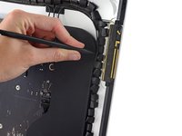
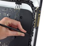
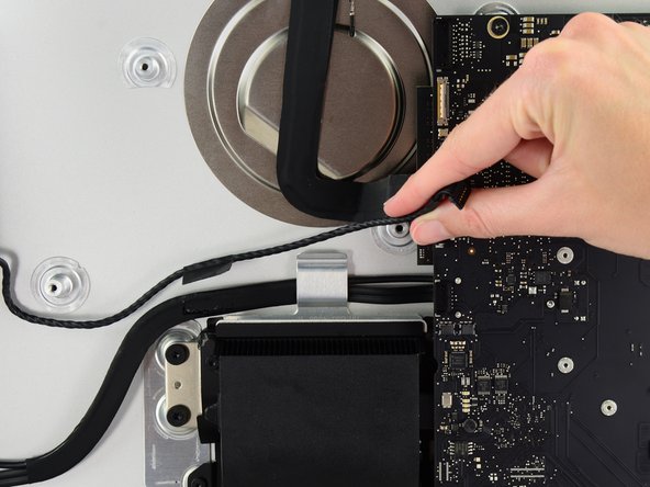
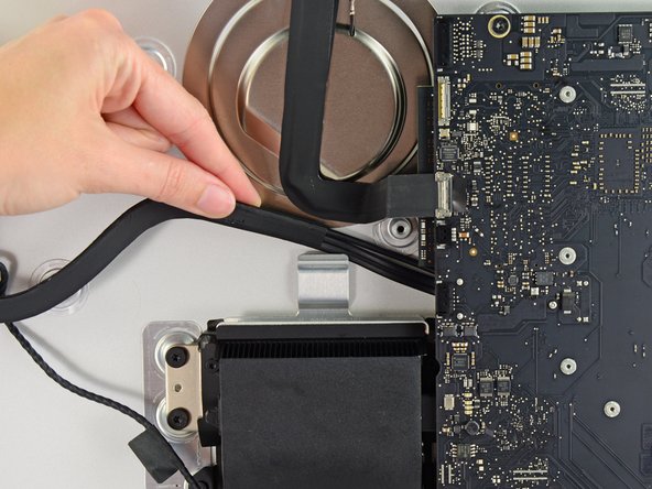
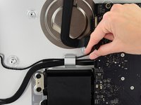
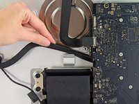
Insert the tip of a spudger between the right speaker and the antenna cable that is routed into the speaker's right side.
-
Run the spudger down along the right side of the speaker to pry the antenna cable from its channel in the right speaker.
-
-
-
Lift the right speaker straight up and remove it from the iMac.
-
-
-
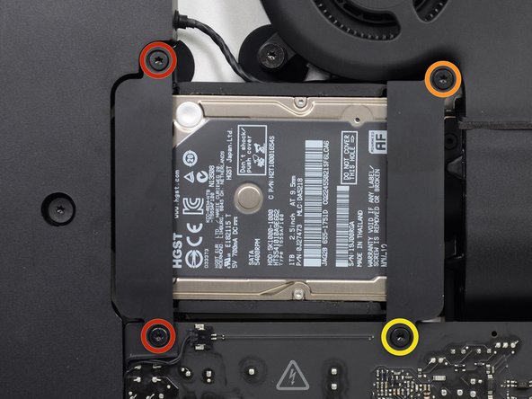
Remove the following screws securing the hard drive bracket to the rear enclosure:
-
Two 21 mm T10 Torx screws from the left-hand hard drive bracket.
-
One 9 mm T10 Torx screw.
-
One 27 mm T10 Torx screw.
-
-
-
Remove the left and right hard drive brackets from the iMac.
-
-
-
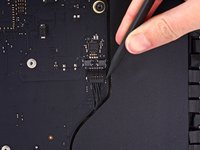
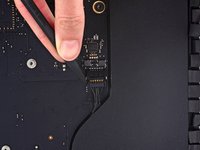
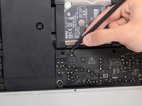
Use the tip of a spudger to push each side of the power button cable connector and gently walk it out of its socket.
-
-
-
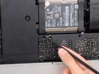
Use the tip of a spudger to push each side of the power supply control cable connector and gently walk it out of its socket.
-
-
-
Remove the two 7.2 mm T10 Torx screws securing the power supply to the rear enclosure.
-
-
-
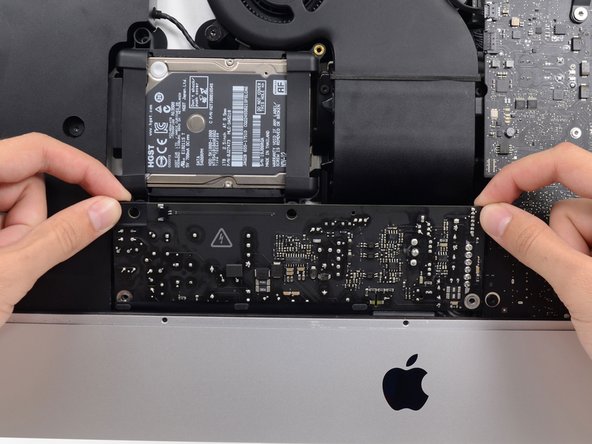
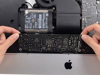
Pull the power supply slightly up and out from the rear enclosure.
-
Rotate the power supply counterclockwise, lifting the right side up about an inch higher than the left.
-
-
-
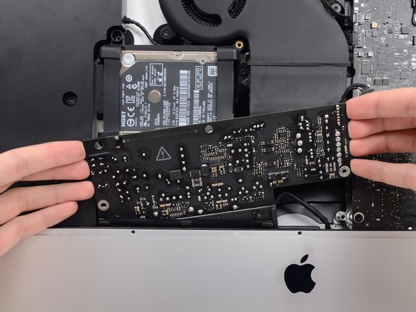
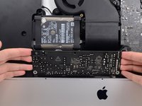
Slide the power supply to the right to clear the screw posts on the rear enclosure.
-
-
-
Rock the power supply forward and remove it from its recess in the rear enclosure.
-
-
-
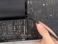
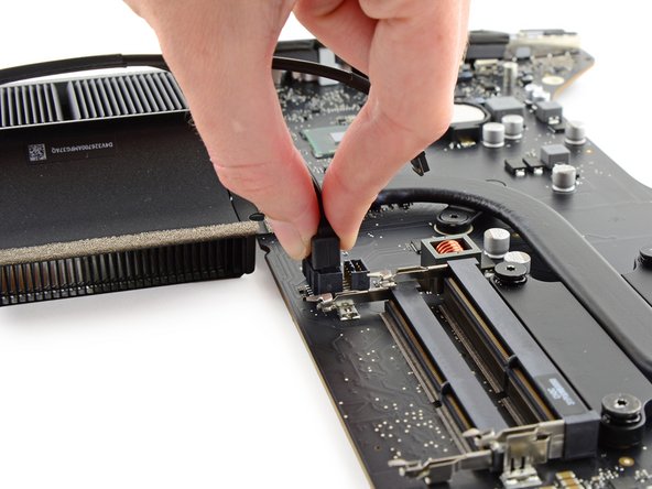
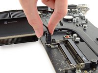
Squeeze the tab on the back side of the DC power cable connector and pull it straight out of its socket on the back of the logic board.
-
-
-
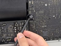
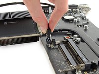
Use the flat end of a spudger to press the clip on the side of the AC inlet cable connector inward.
-
While pressing on the release clip with the spudger, grasp the AC inlet cable, and pull the connector straight out of its socket.
-
-
-
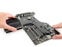
Remove the power supply from the iMac.
-
-
-
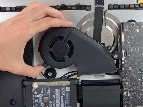
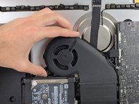
Gently pull the fan cable connector straight away from its socket on the logic board.
-
-
-
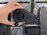
Remove the three 12.3 mm T10 shoulder screws securing the fan to the rear enclosure.
-
-
-
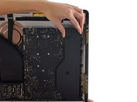
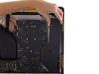
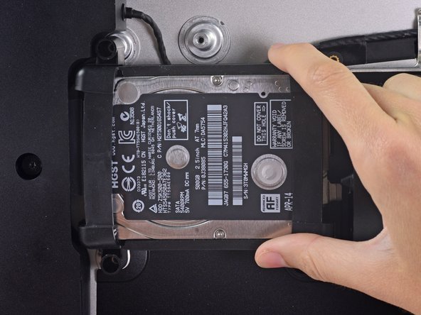
Lift the hard drive from the edge nearest the logic board and pull it slightly out of its recess.
-
-
-
Use a spudger to disconnect the single SATA power and data combo cable by gently prying its large plastic connector away from the hard drive.
-
-
-
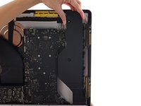
Remove the hard drive assembly from the iMac.
-
-
-
Remove the single 7.2 mm T10 screw securing the hard drive tray to the rear enclosure.
-
-
-
Remove the hard drive tray from the rear enclosure.
-
-
-
Push on each side of the left speaker cable connector with the tip of a spudger and gently walk it out of its socket.
-
-
crwdns2935267:0crwdne2935267:0Tweezers$4.99
-
If necessary, use a pair of tweezers to gently peel the tape securing the left speaker cable to the SATA data/power cable.
-
-
-
De-route the left speaker cable by pulling it straight up out of the retaining clip in the back of the rear enclosure.
-
-
-
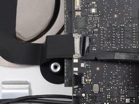
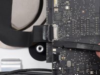
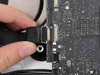
Use the flat edge of a spudger to flip up the metal retaining bracket on the iSight camera cable connector.
-
Pull the iSight camera cable straight out of its socket on the logic board.
-
-
-
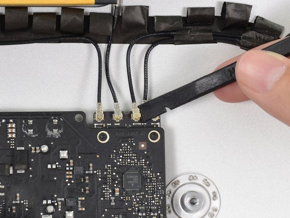
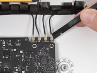
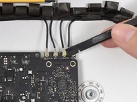
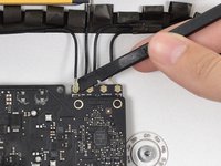
Use the flat edge of a spudger to disconnect each of the four antenna connectors from the AirPort/Bluetooth card.
-
-
-
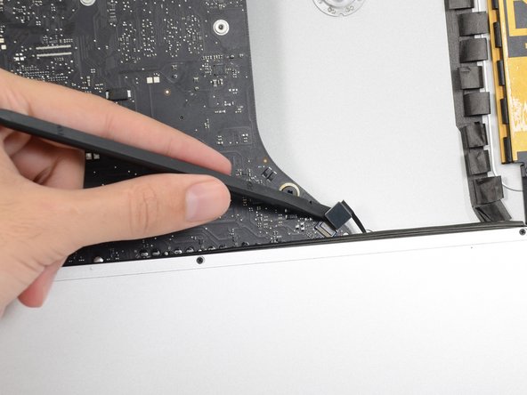
Use the flat edge of a spudger to pry the headphone jack cable connector from its socket on the logic board.
-
-
-
Remove the following screws securing the exhaust duct to the rear enclosure:
-
Two 6.3 mm T8 screws
-
Two 4.7 mm T8 screws
-
-
-
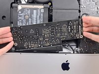
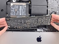
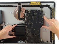
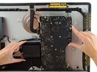
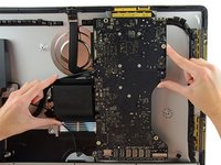
Remove the four 7.2 mm T10 screws securing the logic board to the rear enclosure.
-
-
-
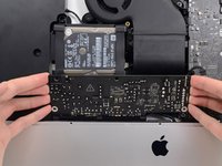
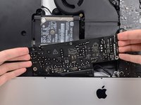
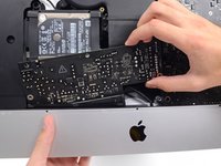
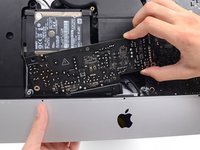
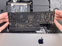
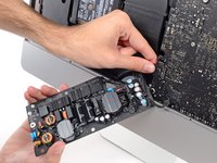
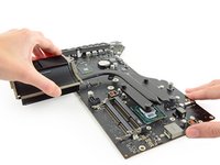
Tilt the top of the logic board away from the rear enclosure.
-
Lift the logic board straight up and out of the iMac.
-
-
-
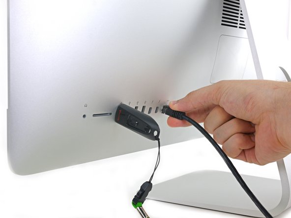
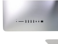
Use a USB flash drive and/or ethernet cable to ensure the logic board is seated correctly while you screw it in.
-
-
-
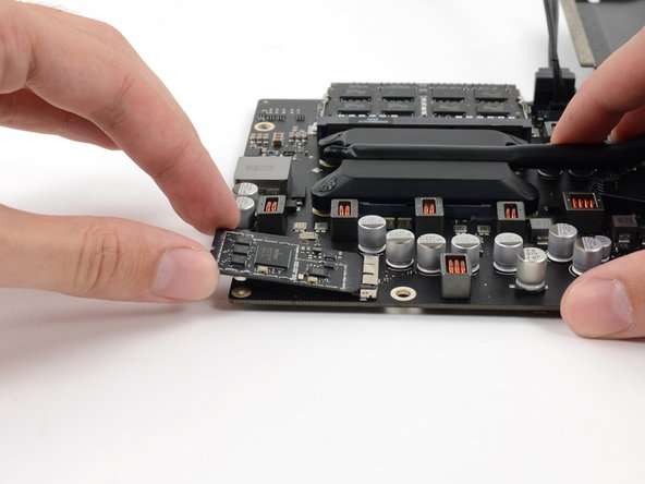
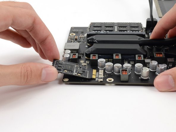
Remove the two 3.2 mm T5 screws securing the AirPort/Bluetooth card to the logic board.
-
-
-
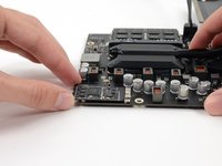
Slightly lift the AirPort/Bluetooth card and pull it straight out its socket.
-
-
-
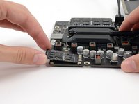
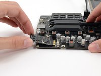
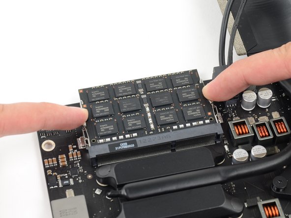
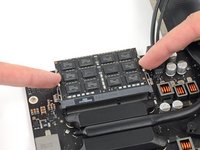
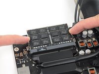
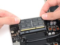
Release the tabs on each side of the RAM module by simultaneously pushing each tab away.
-
Grab the top left and right corners of the RAM module and carefully pull it straight out of its socket.
-
-
-
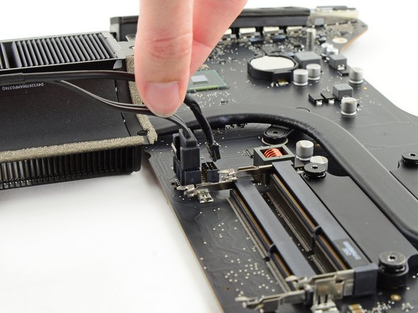
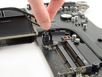
Grasp the hard drive power connector and gently pull it out of its socket on the logic board.
-
-
-
While pressing on the clip with your thumb, lift and disconnect the SATA data connector from its socket on the logic board.
-
-
-
The following screws secure the heat sink to the logic board:
-
Remove the two T8 screws from the exhaust port end of the heat sink.
-
Loosen, but do not remove, the four captive T8 screws securing the CPU end of the heat sink.
-
-
-
Slowly lift and remove the heat sink from the logic board.
-


To reassemble your device, follow these instructions in reverse order.
crwdns2935221:0crwdne2935221:0
crwdns2935229:025crwdne2935229:0


crwdns2947412:06crwdne2947412:0
Followed the guide and unfortunately i couldnt power the mac on after. But i suspect that the logic board or power might have been faulty
Has this iMac a M.2 SSD port? I watched some other disassembly’s from this Mac and there was mentioned, that it has a M.2 port.
Hi! Just pulling one of these apart now and “Yes” there is a proprietary PCIe connector for an SSD — has to be an Apple one though.
Just to add that this Logic Board (Core i5) cannot be simply swapped with Logic board EMC 2742 w/ Core i7!
Hey that button cell on the logic board, will it need replaced? I can’t find info here nor OWC about changing it. I will be going in for upgrades, just picked one of these iMacs up, since I’m going in, don’t want to have to go in again if I don’t have to.