crwdns2933423:0crwdne2933423:0

crwdns2931315:0crwdnd2931315:0crwdne2931315:0

crwdns2862623:0crwdne2862623:0
crwdns2942641:0crwdne2942641:0

crwdns2942213:0crwdne2942213:0

  1. crwdns2935201:0crwdne2935201:0 crwdns2935203:0crwdne2935203:0

    : crwdns2935265:01crwdnd2935265:01crwdnd2935265:02crwdne2935265:0 : crwdns2935265:01crwdnd2935265:02crwdnd2935265:02crwdne2935265:0
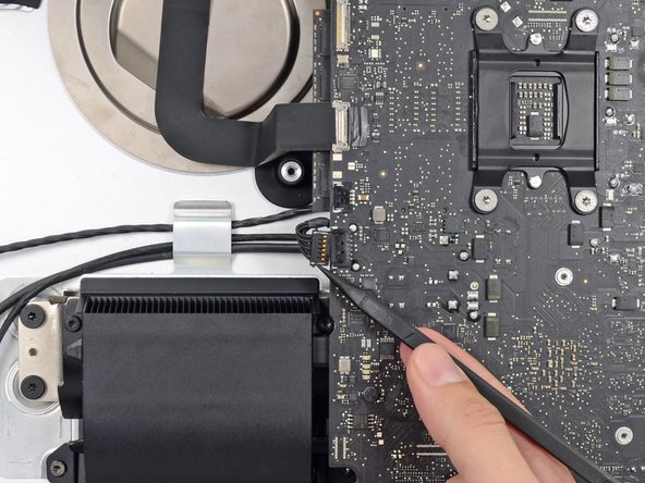
    • Push on each side of the left speaker cable connector with the tip of a spudger and gently "walk" it out of its socket.

  2. crwdns2935201:0crwdne2935201:0 crwdns2935203:0crwdne2935203:0

    : crwdns2935265:02crwdnd2935265:01crwdnd2935265:02crwdne2935265:0 : crwdns2935265:02crwdnd2935265:02crwdnd2935265:02crwdne2935265:0
    • De-route the left speaker cable by pulling it straight up out of the retaining clip in the back of the rear enclosure.

  3. crwdns2935201:0crwdne2935201:0 crwdns2935203:0crwdne2935203:0

    : crwdns2935265:03crwdnd2935265:01crwdnd2935265:03crwdne2935265:0 : crwdns2935265:03crwdnd2935265:02crwdnd2935265:03crwdne2935265:0 : crwdns2935265:03crwdnd2935265:03crwdnd2935265:03crwdne2935265:0
    • In a similar fashion as the previous step, de-route the SATA data and power cables up out of the retaining clip.

  4. crwdns2935201:0crwdne2935201:0 crwdns2935203:0crwdne2935203:0

    : crwdns2935265:04crwdnd2935265:01crwdnd2935265:03crwdne2935265:0 : crwdns2935265:04crwdnd2935265:02crwdnd2935265:03crwdne2935265:0 : crwdns2935265:04crwdnd2935265:03crwdnd2935265:03crwdne2935265:0
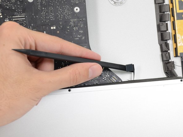
    • Use the flat edge of a spudger to flip up the metal retaining bracket on the iSight camera cable connector.

    • Pull the iSight camera cable straight out of its socket on the logic board.

    • This is a delicate connector that can be easily damaged.

  5. crwdns2935201:0crwdne2935201:0 crwdns2935203:0crwdne2935203:0

    : crwdns2935265:05crwdnd2935265:01crwdnd2935265:03crwdne2935265:0 : crwdns2935265:05crwdnd2935265:02crwdnd2935265:03crwdne2935265:0 : crwdns2935265:05crwdnd2935265:03crwdnd2935265:03crwdne2935265:0
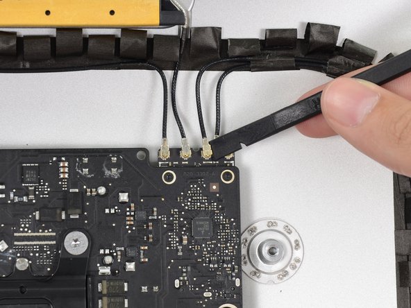
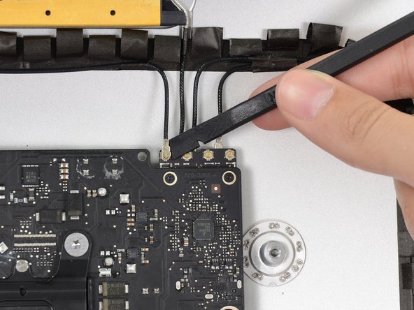
    • Use the flat edge of a spudger to disconnect each of the four antenna connectors from the AirPort/Bluetooth card.

    • Note the original positions for each connector when reconnecting the cables.

  6. crwdns2935201:0crwdne2935201:0 crwdns2935203:0crwdne2935203:0

    : crwdns2935265:06crwdnd2935265:01crwdnd2935265:01crwdne2935265:0
    • If brackets secure the four antenna cables, remove the two T5 Torx screws from the brackets.

  7. crwdns2935201:0crwdne2935201:0 crwdns2935203:0crwdne2935203:0

    : crwdns2935265:07crwdnd2935265:01crwdnd2935265:03crwdne2935265:0 : crwdns2935265:07crwdnd2935265:02crwdnd2935265:03crwdne2935265:0 : crwdns2935265:07crwdnd2935265:03crwdnd2935265:03crwdne2935265:0
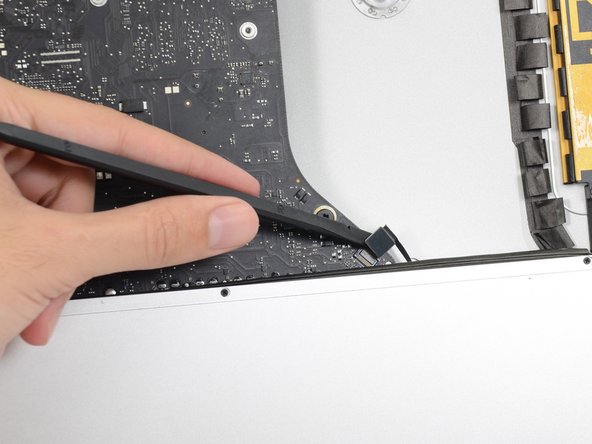
    • Use the flat edge of a spudger to pry the headphone jack cable connector from its socket on the logic board.

    • Push the cable slightly to the right.

  8. crwdns2935201:0crwdne2935201:0 crwdns2935203:0crwdne2935203:0

    : crwdns2935265:08crwdnd2935265:01crwdnd2935265:01crwdne2935265:0
    • Remove the following screws securing the exhaust duct to the rear enclosure:

    • Two 6.3 mm T8 screws

    • Two 4.7 mm T8 screws

  9. crwdns2935201:0crwdne2935201:0 crwdns2935203:0crwdne2935203:0

    : crwdns2935265:09crwdnd2935265:01crwdnd2935265:01crwdne2935265:0
    • Remove the four 7.2 mm T10 screws securing the logic board to the rear enclosure.

    • Depending on the age and model of your iMac, a T9 driver may work best.

  10. crwdns2935201:0crwdne2935201:0 crwdns2935203:0crwdne2935203:0

    : crwdns2935265:010crwdnd2935265:01crwdnd2935265:03crwdne2935265:0 : crwdns2935265:010crwdnd2935265:02crwdnd2935265:03crwdne2935265:0 : crwdns2935265:010crwdnd2935265:03crwdnd2935265:03crwdne2935265:0
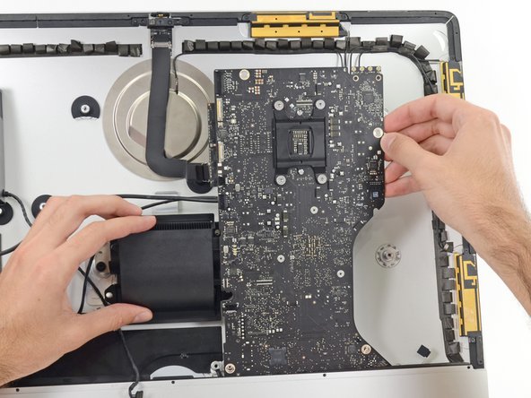
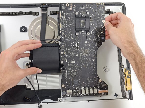
    • Tilt the top of the logic board away from the rear enclosure.

    • Lift the logic board straight up and out of the iMac.

    • Be careful not to snag the board on any of the rear case's screw posts.

    • The I/O boards at the bottom of the logic board will be the greatest challenge. It is recommended to pull gently to avoid any damage.

    • During reassembly of the logic board, pay attention to the position of the I/O connectors. When the board is back in the case, insert a USB or Thunderbolt cable into one of the connectors to align it perfectly.

crwdns2935217:0crwdne2935217:0

Sam Goldheart

crwdns2935283:010/18/12crwdne2935283:0

465,936 crwdns2915208:0crwdne2915208:0

crwdns2935297:0538crwdne2935297:0

crwdns2915084:0crwdne2915084:0

iFixit crwdns2935289:0iFixitcrwdne2935289:0

Staff

crwdns2931471:0135crwdne2931471:0

crwdns2935297:017,277crwdne2935297:0

crwdns2944067:00crwdne2944067:0

crwdns2917038:0crwdne2917038:0

crwdns2936625:0crwdne2936625:0:

crwdns2936751:024crwdne2936751:0 0

crwdns2936753:07crwdne2936753:0 1

crwdns2936753:030crwdne2936753:0 13

crwdns2942667:0crwdne2942667:0 114