crwdns2915892:0crwdne2915892:0
You can install hard drives up to 9.5mm thick.
crwdns2942213:0crwdne2942213:0
-
-
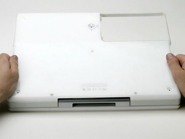
Use a coin to rotate the battery locking screw 90 degrees clockwise.
-
Lift the battery out of the computer.
-
-
-
Pull the keyboard release tabs (highlighted in red) toward you and lift up on the keyboard until it pops free.
-
If the keyboard does not come free, use a small flathead screwdriver to turn the keyboard locking screw 180 degrees in either direction and try again.
-
Flip the keyboard over, away from the screen, and rest it face-down on the trackpad area.
-
-
-
Push the wire clasp toward the AirPort card and pull it up to free it from the RAM shield.
-
-
-
Grasp the clear plastic tab on the AirPort card and pull toward the right.
-
-
-
Hold the AirPort card in one hand and use your other hand to remove the antenna cable.
-
-
-
Remove the two Phillips screws that secure the RAM shield.
-
-
-
Grasp the metal bracket on top of the RAM shield and pull upward to remove the shield.
-
-
-
Pull the keyboard cable up from the logic board, holding the cable as close to the connector as possible.
-
-
-
Use a pin to remove the three rubber feet from the lower case.
-
-
-
Remove the three newly-revealed Phillips screws.
-
-
-
Use a spudger or small flathead screwdriver to pry up the three metal rings that housed the rubber bumpers.
-
-
-
Remove the three hex screws using a T8 Torx screwdriver.
-
-
-
Remove the two Phillips screws on either side of the battery contacts.
-
-
-
-
Push the thin rims of the lower case surrounding the battery compartment in, bending them past the tabs, and then lift up to free that corner of the lower case.
-
-
-
Use a small flathead screwdriver to pry out the slot's lower rim and pull up on the lower case to free the slot from the tabs holding it.
-
-
-
Run a spudger along the seam between the lower case and upper case on the front of the computer to free the tabs locking the lower case.
-
Pull up on the lower case and continue to use the spudger as necessary until you hear three distinct clicks.
-
-
-
Continue to run the spudger around the front, right corner.
-
-
-
Once the front and sides of the lower case are free, turn the computer so that the back is facing you.
-
Pull the lower case up and toward you until the back tabs pop free.
-
-
-
Remove the small greasy springs with white plastic caps from either side of the battery contacts.
-
-
-
Remove the following 9 screws on the bottom of the computer:
-
Three 3 mm Phillips around the battery compartment.
-
Three 5 mm Phillips on the left and bottom edges.
-
Three 14.5 mm Phillips on the top and right edges (you may have to peel back the foil tape to reveal the screw near the security lock slot).
-
-
-
Turn over the computer and open it.
-
Pry up the magnet covering a Phillips screw near the middle of the computer.
Mine didn't have a screw under the magnet.
crwdns2936937:0TekMaccrwdne2936937:0
Mine didn't have a screw under the magnet.
I don't mean that a screw was missing, I'm saying that there is no screw or screw hole installed on my 14" in that location. The other steps were dead-on though.
No magnet, screw or screw hole on my upper case either.
Not all G3 Dual USB iBooks have a screw underneath the magnet, so the magnet need not be removed in these cases and will not hinder the removal of the top.
Some iBooks like the 16 VRAM model have the magnet but there is no screw behind it.
Check to see if your model has a screw under the magnet first. If you can lift up the area around the magnet there is no screw to deal with.
900MHz model does not have a screw here.
-
-
-
Remove the following 3 screws on the edges of the keyboard area:
-
Two 6 mm Phillips underneath the keyboard area.
-
One 9 mm Phillips above the keyboard area.
There is a forth screw underneath the magnet: top center of keyboard area.
-
-
-
With your fingernails, grasp the locking bar on either side and pull up a small amount (about 1/16" or 2 mm).
-
After disengaging the locking bar, slide the cable out of the connector.
-
-
-
Loosen the trackpad connector by pulling the top piece up slightly, freeing the trackpad ribbon.
-
Slide the orange trackpad ribbon out of the connector.
-
-
-
Use a straightened paperclip to open the optical drive tray, and pull it out about halfway.
-
-
-
Lift the upper case from the left side and use your other hand to pull out the right side in order to clear the power receptacle.
-
-
-
Lift the upper case enough to disconnect the blue and white power cable from the logic board.
-
Using your fingernails or a dental pick, carefully pry the connector from its socket.
hello...while i was at step 27 i pulled the connector too much and i broken the socket from the logic board!! I used a glue to put it back but now doesen't turn on the computer...any idea??? :)
-
-
-
Lift the upper case off completely and disconnect the red and black speaker cable from the logic board.
-
-
-
Remove the following 16 screws:
-
Five 3 mm Phillips (these have smaller heads than the others).
-
Three 5 mm Phillips.
-
Eight 6 mm Phillips.
-
-
-
Peel back three strips of yellow tape in the bottom, left corner.
-
Peel back one strip of foil tape near the audio-out port, one near where the trackpad connects to the logic board, and one near where the screen latch used to be.
-
-
-
Lift the top shield up from the right side, minding the upper left corner, which may catch on the metal framework.
-
-
-
Remove the single Phillips screw to the right of the hard drive connector.
I have the 800 Mhz model and I had a T7 Torx here, instead of a Phillips head.
-
-
-
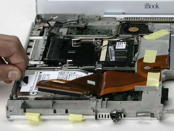
At the front edge of the hard drive, lift up on the transparent orange tape to disconnect the ribbon cable from the main board.
-
-
-
Peel back the black tape to free the microphone cable from the hard drive.
-
-
-
Lift the hard drive out of the computer and turn the hard drive over. Use the transparent orange loop to disconnect the hard drive ribbon cable from the hard drive.
-
-
-
Remove the metal brackets from either side of the hard drive (if they're still there).
-
-
-
Remove two T8 Torx screws from either side of the hard drive (four screws total).
-


To reassemble your device, follow these instructions in reverse order.
To reassemble your device, follow these instructions in reverse order.
crwdns2935221:0crwdne2935221:0
crwdns2935229:036crwdne2935229:0
crwdns2935103:0crwdne2935103:0

crwdns2947412:03crwdne2947412:0
I don't think you have to remove the bottom case to replace the hard drive, at least on the iBook 800MHz 32MB VRAM.
Just replaced the original 20GB HDD with a 40GB in an iBook G3/600 (mid 2002); removal of the case bottom IS necessary on this model. It was more "tedious" than "difficult" (37 steps in, 37 steps out), although I had previous experience on this same machine upgrading RAM to 640MB and installing an AirPort card.
step 21 is not necessary and if you care about the mac having it’s original sticker I would not advise doing what it says… The “magnet” is not removable and if the system is original the sticker will not peal up easily.