crwdns2933803:05crwdne2933803:0
crwdns2933797:0David Dcrwdnd2933797:0crwdne2933797:0
crwdns2936043:0crwdne2936043:0 crwdns2933505:0crwdne2933505:0 David D
- crwdns2933769:0crwdne2933769:0
- crwdns2933771:0crwdne2933771:0
- crwdns2933801:0crwdne2933801:0
crwdns2933807:0crwdne2933807:0
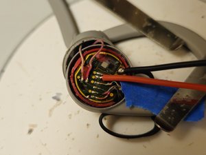
| + | [title] Charging Lead Attachment |
|---|---|
| + | [* black] With the earpiece removed, we can get access to the battery charging terminals. Identify the location of the cell positive and negative terminals. |
| + | [* black] The negative terminal (cell ground) is a large soldered tab. The positive terminal is the second lead from the square IC chip. |
| + | [* black] Remove the silastic wire bonding to expose the ground and positive lead. De-solder and tape back the cell positive ground to protect the unit's electronics from the charging current in the next step. |
| + | [* black] Solder appropriately colored wires on to the two terminals. |
| + | [* black] Check battery voltage, it should be at or near 0V. |
crwdns2933777:01crwdne2933777:0
crwdns2933779:0crwdne2933779:0

crwdns2915182:0crwdne2915182:0
crwdns2933777:02crwdne2933777:0
crwdns2933779:0crwdne2933779:0
crwdns2915182:0crwdne2915182:0