crwdns2915892:0crwdne2915892:0
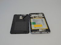
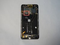
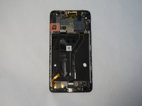
The LED screen and touchscreen (digitizer) are one unit and make up the frame of the phone. You will essentially be removing all of the internal components of the phone and placing them in a new housing.
crwdns2942213:0crwdne2942213:0
-
-
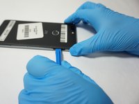
Turn the device on it side with the buttons away from you.
-
Using the SIM Card Eject Tool, insert the narrow end into the ejection hole.
-
Press firmly into the hole until the SIM card tray pops out far enough to grab with your fingers.
-
-
-
Pull the tray out with your fingers .
-
Remove the SIM card.
The tray is the part I require. Is there a part or place I can get to.
-
-
-
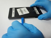
Remove the one T2 screw from the side of the phone near where the SIM card tray was.
This step is not at all necessary. Just skip it, it will make no difference.
It is smaller than T2, none of my 3 ifixit kits would fit it.
-
-
-
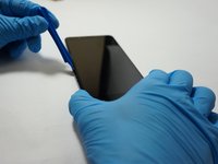
Insert a plastic opening tool into the space where the SIM card tray used to be.
-
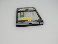
Gently pry the back away form the phone frame until you hear and audible click of the back separating.
To be clear, the silver “rim” does not separate from the black portion of the frame that extends around the back and sides and covers both logic boards; this is all one single piece.
Be extra careful of the area near he power button, where the trim is thin and delicate and may break easily (especially if you’re trying to separate the silver from the black ;)
-
-
-
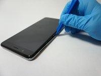
Insert the plastic opening tool into the space you created between the phone back and frame.
-
Slide the plastic opening tool along the outside of the phone, underneath the back, to separate the rest of the clips holding the back onto the frame.
-
-
-
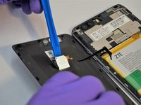
Rotate the back over to the side, being careful not to damage the fingerprint sensor ribbon cable.
-
Use a plastic opening tool to separate the fingerprint sensor from the back of the phone.
-
Set the phone back aside.
if you leave the finger print scanner you can remove the screws and snap the back plate back on then once the second plastic frame is removed you can then disconnect the other end of the cable
-
-
-
Remove the 6 silver 2.9mm screws from the back of the phone with a JIS #000 bit.
-
Remove the 11 black 3.5mm screws with the same JIS #000 bit.
-
-
-
Turn the phone over, with the screen up.
-
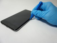
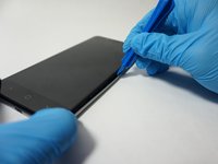
Insert the opening tool between the screen and the silver trim that surrounds it.
-
Run the plastic opening tool around the circumference of the phone to separate the clips of that hold the trim to the frame.
-
-
-
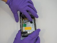
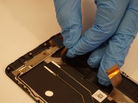
Turn the phone back over, with the screen down.
-
Lift the trim piece off of the phone and set aside.
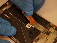
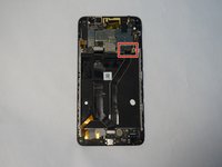
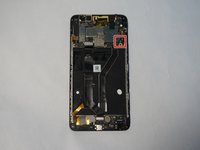
There is metal mesh tape covering the area in the center, just above the battery, to the right of the fingerprint sensor cable connector. Remove this tape to expose a clip that holds the frame in place.
-
-
-
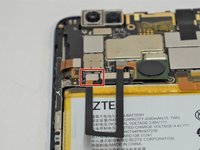
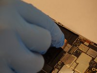
Using a plastic opening tool, separate the fingerprint ribbon connector from the motherboard.
This step is not necessary if you’re careful not to rip the ribbon cable.
-
-
-
crwdns2935267:0crwdne2935267:0Tweezers$4.99
-
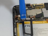
Use a pair of tweezers to carefully pull up on the tape securing the connector.
-
This will undo the connector as well.
-
-
-
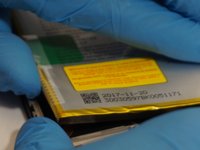
Starting at the bottom left corner of the battery, use the wide end of the spudger as a wedge to get underneath the battery.
-
Insert a plastic opening tool into the space created by the spudger and CAREFULLY begin to pry around the edge of the battery.
-
Once the battery is separated for enough from the phone, use your hands to fully remove the battery, using the wide end of the spudger to scrape off adhesive where necessary.
It would be nice to know if you needed to heat it up how you are suppose to do that. There are no instructions for that.
-
-
crwdns2935267:0crwdne2935267:0Tweezers$4.99
-
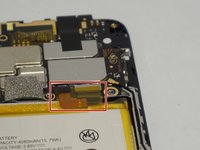
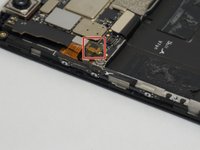
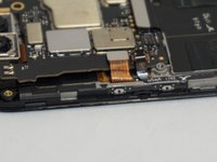
Using a set of tweezers, pull off the small piece of tape on top of the ribbon cable connector on the left side of the motherboard.
-
-
-
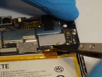
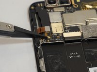
Use a plastic opening tool or spudger to scrape the glue away from the ribbon cable.
-
-
-
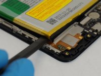
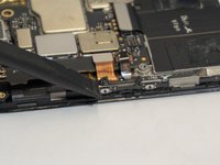
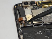
Using a plastic opening tool or spudger, open the zip connection by prying up on the right (black) side of the connector.
-
Using the tweezers, carefully pull the the ribbon cable out of the connector.
-
-
-
Using a plastic opening tool or tweezers, pry the edge of the button strip away from the phone.
-
Once all of the buttons are free, the whole assembly should simply lift out.
-
-
-
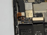
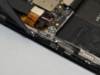
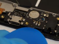
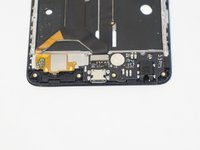
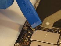
Use a spudger to pry up the the antenna connector on the top right of the charging port card.
-
-
-
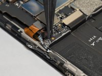
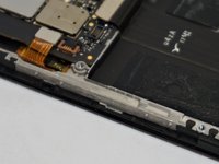
Use a plastic opening tool to pry up and remove the primary connector for the card, located on the top left of the card.
-
-
-
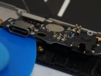
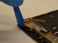
Use a plastic opening tool, spudger, or opening pick to separate the bottom edge of the card away from the phone.
-
Lift the bottom edge of the card high enough that you can grab it with your fingers, and simply remove it from the phone.
Corners may have adhesive. Force may be required to pry the board up. Don’t be scared.
Is the microphone located on the board?
-
-
-
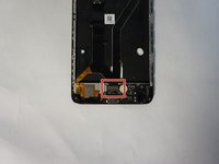
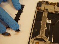
Use a plastic opening tool to lift the lower connection cable, which is held on by adhesive, off of the phone frame.
-
-
-
Use the plastic opening tool to separate the connector ribbon from the bottom center of the phone.
-
-
-
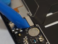
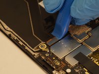
Use a plastic opening tool to separate the first motherboard connector from the bottom left of the motherboard.
-
-
-
Starting from the connector you just removed, carefully peel the ribbon cable away from the phone.
-
Set the ribbon cable aside.
-
-
-
Use a plastic opening tool to disconnect the second motherboard connector from the bottom right of the motherboard.
-
-
-
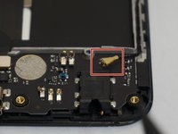
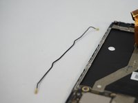
Use a plastic opening tool to disconnect the upper antenna connector.
-
Remove the antenna from the phone and set aside.
-
-
-
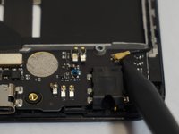
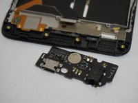
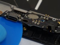
Use the plastic opening tool to remove the charging port card of the phone.
-
-
-
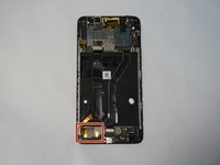
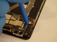
Use a plastic opening tool to disconnect the digitizer ribbon connector located on the opposite side of the antenna connection and near the side button connector.
-
-
-
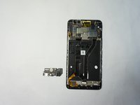
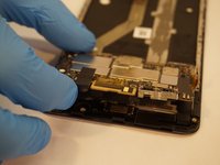
Carefully lift the motherboard out of the frame.
-
-
-
Use a plastic opening tool or spudger to remove the earpiece from the frame, located near the top of the phone.
-


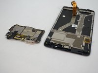

To reassemble your device, follow these instructions in reverse order.
To reassemble your device, follow these instructions in reverse order.
crwdns2935221:0crwdne2935221:0
crwdns2935229:013crwdne2935229:0

crwdns2915084:0crwdne2915084:0

The Citadel Military College of South Carolina, Team S3-G7, Eggleston Fall 2018 crwdns2935289:0The Citadel Military College of South Carolina, Team S3-G7, Eggleston Fall 2018crwdne2935289:0
CMCSC-EGGLESTON-F18S3G7
crwdns2931471:04crwdne2931471:0
crwdns2935297:012crwdne2935297:0
crwdns2947412:02crwdne2947412:0
Thanks! This helped loads with my repair.
Thanks for the tutorial. It helped a ton and was easy to follow. I would add the screen replacement from the frame portion of the assembly.