crwdns2915892:0crwdne2915892:0
Get back to your gaming by replacing your Xbox 360 wireless controllers logic board.
crwdns2942213:0crwdne2942213:0
-
-
Depress the battery release button on the top of the controller.
-
Remove the battery holder from the controller.
-
-
crwdns2935267:0crwdne2935267:0Tweezers$4.99
-
Use a pair of tweezers to peel the barcode sticker from the battery compartment.
-
-
-
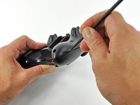
Remove the seven 9.3 mm T8 Security Torx screws securing the rear case to the front case.
Any recommendation on which set of Security Torx tools to use? I've already purchased 2 kits, one of those being sold as "Xbox controller tools" but the diameter of the head does not fit the hole on the controller and that's critical for the 2 screws on the bottom. The tools must obviously be thinner in diameter and long enough to get there.
How to open an XBOX 360 controller without a special screwdriver. http://www.instructables.com/id/How-to-o... Works perfectly.
A lot of thanks for your comment. It's very usefull
Echedey -
I picked up a handy torx key set from Auto Zone. Was about $10, no lose driver bits. has both sizes you need to repair the controller and the console. Here's the link:
It doesn't really matter which set of bits you by or what brand makes them, Torx bits (and the security versions of them) are generic & come in standardized sizes. You do not need a special "xbox" tool kit, you just need a size 8 torx security bit, no matter what brand makes the bit/kit. Those types of "specialty kits" are usually just collections of generic bits that you can buy at a hardware store in a regular bit set. The difference is that a general bit set will have bits for screws that a specific item doesn't have in it, whereas a specialty kit will only include bits for the types & sizes of fasteners used in the specified item.
BTW, with the smaller sizes of torx security bits you can try breaking off the little post in the middle with needlenose pliers or something else that can fit in the there. Even if the post doesn't break off cleanly, it's usually short enough to fit a regular (non security) torx bit in the slot.
-
-
crwdns2935267:0crwdne2935267:0Spudger$2.99
-
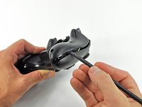
Insert a Spudger between the front and rear cases along the left edge of the controller.
-
Rotate the spudger toward the front of the controller, prying the two cases apart.
-
-
-
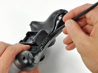
Insert a spudger between the front and rear cases, near the headphone jack.
-
Rotate the spudger toward the front of the controller to pry the two cases apart.
-
-
-
-
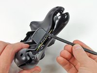
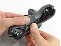
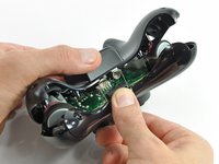
Grasp the controller by the battery compartment and the headphone jack.
-
Lift the battery compartment away from the headphone jack, separating the rear case from the front case and logic board.
The RB / LB bar will fall away easily as you handle the upper case and logic board; just be prepared for it.
Good information
-
-
-
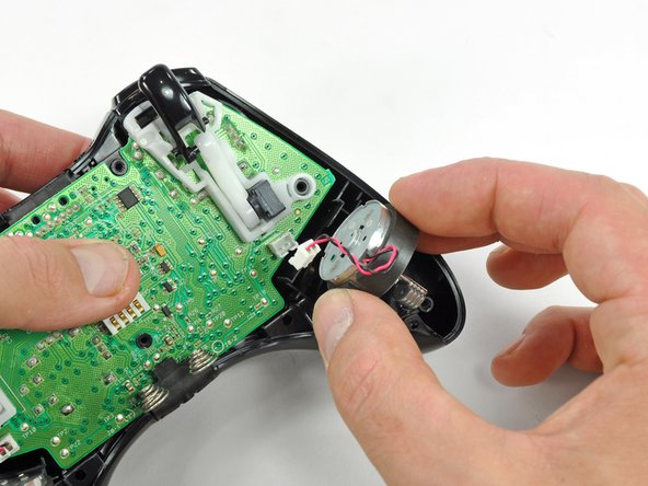
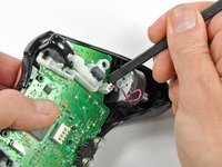
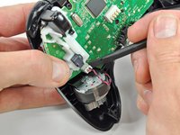
Use the flat end of a spudger to remove the vibration motor cable, moving it upward from its socket on the logic board.
-
Lift the vibration motor out of the front case.
-
-
-
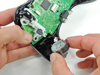
Remove the vibration motor from the other side of the controller using the same method previously described.
The opposite was true for the controller I just opened. It was the left motor counterweight (as you hold the controller normally) which had more weight. Perhaps it doesn't matter which goes where?
For anyone reading this in the future, it does matter. The way you had them originally is the correct way.
-
-
-
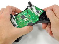
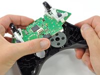
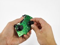
Lifting from the headphone jack and power plug, remove the logic board from the front case.
What if you're having difficulty taking the logic board out?
In my experience with my controller, the logic board lifts out very easily, there are no tabs or fasteners holding it in.
So, if you're having difficulty taking the logic board out, call a friend with average hand dexterity & motor skills to do it for you.
If the controller is a bit old, the center plastic screw holder might have swollen and will need a little stenght to release the logic board.
-
-
-
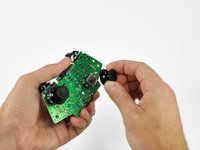
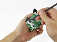
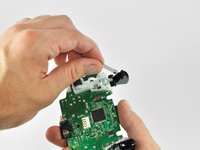
Grasp the right analog stick and pull the cover off its mount peg.
-
-
-
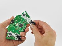
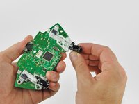
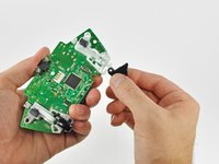
Remove the left analog stick cover using the same procedure previously described.
-
-
-
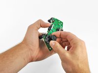
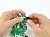
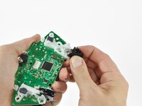
Using your thumb and forefinger, push the left trigger toward the right side of the controller. Simultaneously push the trigger control arm in the opposite direction.
-
Push the trigger arm downward.
-
-
-
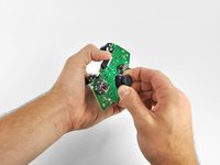
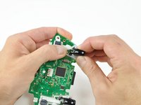
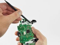
Insert the edge of a spudger in between the trigger and the trigger assembly near the left edge. Pry the housing away from the catch on the trigger.
-
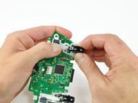
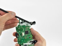
Using the previously described technique, pry the housing on the right edge away from the trigger.
-
Rotate the trigger away from the logic board, past its housing.
-
-
-
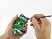
Using a spudger, pry the trigger spring off its peg on the trigger housing.
-
Pull the trigger spring out of the trigger.
-
-
-
Slide the trigger toward the right side of the logic board, and rotate it clockwise.
-
Remove the right trigger from the logic board.
This is a removal guide not a replacement guide. I need steps to putting the trigger back in now.
My trigger works by moving in and out but it is constantly either working or constantly not, when i press the home screen it switches between the two……help please
-


To reassemble your device, follow these instructions in reverse order.
To reassemble your device, follow these instructions in reverse order.
crwdns2935221:0crwdne2935221:0
crwdns2935229:042crwdne2935229:0


crwdns2947412:08crwdne2947412:0
Does it matter which side the motors are returned to? I think I may have swapped positions with my two motors.
Any guides for troubleshooting the test points on the board as to determine why the left trigger doesn't aim during gameplay? I've replaced the potentiometer with a brand new one but still nothing, everything else works perfectly …thoughts?
bad connection down the Vdc supply, gnd, or sense pin paths? Or a blown channel on the ADC that reads the potentiometer and converts the value to digital. If the ADC is integrated inside the main chip, its toast. Its also possible another component along the signal path may be faulty. Like a capacitor gone short for some reason. Basically its break out the multimeter and start poking stuff time.
Tank R -
I don't need a removal guide I need a diagram that shows me how to put the trigger on a button on top so a child with deformed fingers can use it. The triggers apparently have hall type sensors.
I havent been inside my official remote yet, but if the unofficial ones Ive scrapped and/or repaired are any indication the triggers are potentiometers, not hall effect sensors. If you're fine with simple binary control (ie, on off, and not the analog sweep of values) then just wire the center pad and what ever side the wiper moves towards (whichever side drops in resistance when going to full deflection) to a button. If that doesnt work, try center and the other pin.
Tank R -
The logic board won't come out, and I don't want to force it out. Any ideas on how to take it out?
Any guide to checking traces and components on the circuit board for the radio frequency crystal and antenna as have a controller that does not sync though powers on and light cycles correctly after sync button is pressed
Algun tutorial para reparar el Star del mando ya cambié membrana y sigue con el fallo, cabe mencionar que lo e limpiado con isopropílico y tampoco