crwdns2915892:0crwdne2915892:0
This guide is basically a full teardown of the lower half of the laptop. Keep in mind when working on it that all of the plastic parts of the WinBook XP5 are extremely brittle. Avoid stressing them as much as possible. If you haven't reinforced the display hinge mounts yet, I would recommend leaving the laptop open at all times. When you need to access the bottom of the laptop, just hang the display off the side of your table.
-
-
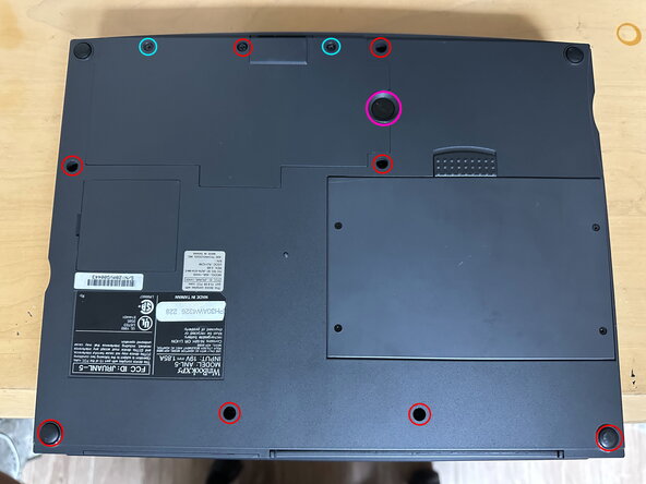
Remove the 8 large case screws, which are circled red. Two of them are hidden under the rear rubber feet. Also remove the two smaller screws, which are on the CPU and memory access door.
-
Remove the single coin screw that secures the hard drive in place.
-
Remove the main battery by pulling the release latch and levering it out, starting at the latch side. You may need to use a pry tool to do this.
-
-
-
With all screws removed, begin to lift the CPU/Memory door up off of the computer, starting from the front edge. Once you begin to feel resistance when moving it up, gently pull it towards you until it comes free from the computer.
-
-
-
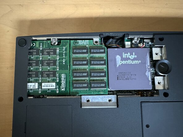
Remove the four highlighted screws. The heatsink will likely be stuck to the CPU via the thermal pad. To remove it, grab a hold of the leftmost side of the heatsink (as viewed from the perspective of this photo) and carefully wiggle it back and forth until it comes free.
-
-
-
In order to remove the motherboard later on, the CPU cache card has to be removed. It is the card in the middle, between the CPU and the RAM card.
-
It is held in place via two press-fit connectors, one at the top and the other at the bottom. Use a spudger or other pry tool to carefully lever it out of the connectors. Be careful not to knock any components off of the motherboard while doing this.
-
While you're here, also disconnect the CPU fan's 2-pin power cable.
-
-
-
-
Flip the laptop over and (carefully!) open the hinges, if the lid was shut before.
-
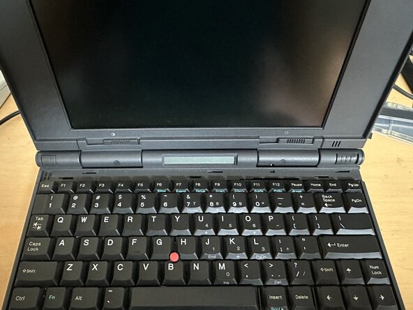
To remove the keyboard, slide the retention bar above the keyboard to the right, then pull it out. Once removed, the keyboard can be lifted up and sat against the display.
-
The keyboard has three cables coming out of it, which plug into ZIF connectors on the motherboard. Once disconnected, the keyboard can be lifted fully out of the laptop.
-
-
-
Your XP5 will have one of three pointing devices installed, which are modular - a TrackPoint button module, a trackball (what I have), or a trackpad. They are all removed the same way.
-
With the keyboard removed, lift the module free from the laptop, starting from the keyboard side. Disconnect its 5-pin cable, which is plugged into a press fit connector.
-
-
-
At this point, we can remove the display and palmrest assembly all at once.
-
Disconnect the cables for the display, status LCD, power button, suspend button, and lid latch. All of these are press-fit connectors, except for the status LCD cable, which is a ZIF connector.
-
Remove the two highlighted screws in the second image.
-
It is clear from the design of the laptop that the modem (if installed) was intended to be removed before the palmrest. However, this requires removing the cover around the modem port, which is now too brittle to remove without damaging it. It is possible to remove the palmrest with the modem installed, it just takes a bit of finagling.
-
-
-
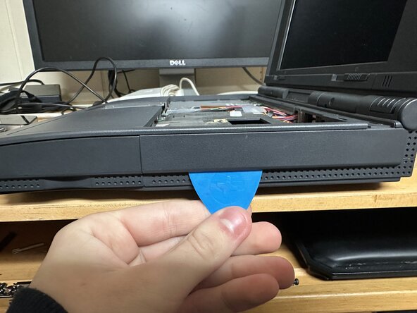
Insert a plastic clip between the palmrest and lower case at the front, as shown in the photo. Slide the pick to the right to release all the clips at the front of the laptop. Then, pop one more clip on the right side. After this, you should be able to very carefully begin lifting the upper half off the laptop.
-
You now have to maneuver the two halves free. The upper half will catch on the floppy drive eject button, and then also on the modem, as it was originally intended to be slid out of the laptop first. With care, you should be able to clear both parts.
-
As you're lifting it free, you will have to disconnect two additional cables, which were previously hidden under the left palmrest. These are the connectors for the speakers and microphone.
-
After disconnecting those last two connectors, the two halves should be separated.
-
-
-
Remove the modem by sliding it free from its connector
-
Remove the floppy drive by removing the screw highlighted in the photo, disconnecting its ribbon cable, and then lifting the drive out of the computer.
-
Remove the hard drive by sliding it free from its connector.
-
-
-
At this point, the motherboard can be lifted free from the bottom case. You can remove the attached DC/DC board prior to pulling the motherboard out, but I always found it more convenient to just pull them out as one piece.
-


To reassemble your device, follow these instructions in reverse order.
To reassemble your device, follow these instructions in reverse order.
