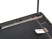
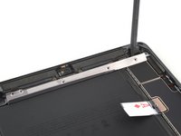
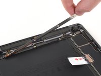
crwdns2933423:0crwdne2933423:0

Upper Component Bracket Removal

crwdns2862623:0crwdne2862623:0
crwdns2942641:0crwdne2942641:0

crwdns2942213:0crwdne2942213:0

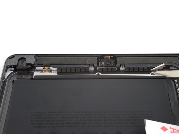
  1. Upper Component Bracket Removal, Remove the upper component bracket: crwdns2935265:01crwdnd2935265:01crwdnd2935265:02crwdne2935265:0 Upper Component Bracket Removal, Remove the upper component bracket: crwdns2935265:01crwdnd2935265:02crwdnd2935265:02crwdne2935265:0
    • Carefully peel the LCD buffer tape up off of the upper component bracket.

  2. Upper Component Bracket Removal: crwdns2935265:02crwdnd2935265:01crwdnd2935265:01crwdne2935265:0
    • Use a Phillips screwdriver to remove the five screws securing the upper component bracket.

    • Three 1.4 mm-long screws

    • Two 1.9 mm-long screws

  3. Upper Component Bracket Removal: crwdns2935265:03crwdnd2935265:01crwdnd2935265:03crwdne2935265:0 Upper Component Bracket Removal: crwdns2935265:03crwdnd2935265:02crwdnd2935265:03crwdne2935265:0 Upper Component Bracket Removal: crwdns2935265:03crwdnd2935265:03crwdnd2935265:03crwdne2935265:0
    • Use the pointed end of a spudger to lift up the upper component bracket until you can grip it with your fingers.

    • Remove the upper component bracket.

    • You may need to peel the upper component bracket off of some tape securing it to the logic board.

crwdns2915888:0crwdne2915888:0

To reassemble your device, follow these instructions in reverse order.
Robert Boyd

crwdns2935283:002/01/21crwdne2935283:0

29 577 crwdns2915208:0crwdne2915208:0

crwdns2935297:094crwdne2935297:0

crwdns2947412:00crwdne2947412:0

crwdns2917038:0crwdne2917038:0

crwdns2936625:0crwdne2936625:0:

crwdns2936751:024crwdne2936751:0 0

crwdns2936753:07crwdne2936753:0 0

crwdns2936753:030crwdne2936753:0 8

crwdns2942667:0crwdne2942667:0 42