crwdns2933423:0crwdne2933423:0

Turtle Beach Elite 800 Transmitter Contact Pins Replacement

crwdns2942213:0crwdne2942213:0

  1. Turtle Beach Elite 800 Transmitter Contact Pins Replacement, Transmitter Contact Pins: crwdns2935265:01crwdnd2935265:01crwdnd2935265:02crwdne2935265:0 Turtle Beach Elite 800 Transmitter Contact Pins Replacement, Transmitter Contact Pins: crwdns2935265:01crwdnd2935265:02crwdnd2935265:02crwdne2935265:0
    • Begin by flipping over the transmitter, and removing the padding from the underside of it. This will reveal the screws to take apart the device.

  2. Turtle Beach Elite 800 Transmitter Contact Pins Replacement: crwdns2935265:02crwdnd2935265:01crwdnd2935265:03crwdne2935265:0 Turtle Beach Elite 800 Transmitter Contact Pins Replacement: crwdns2935265:02crwdnd2935265:02crwdnd2935265:03crwdne2935265:0 Turtle Beach Elite 800 Transmitter Contact Pins Replacement: crwdns2935265:02crwdnd2935265:03crwdnd2935265:03crwdne2935265:0
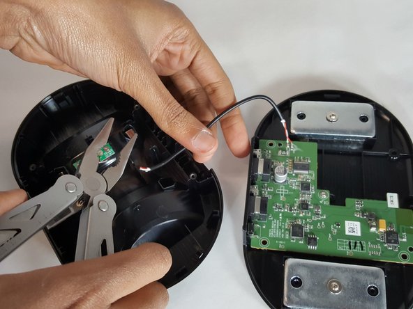
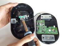
    • Remove the screws ( 11.27mm Phillips head) and open up the transmitter to reveal the internal components. Carefully pry open the transmitter, and use caution when opening it up as to not sever the wire.

  3. Turtle Beach Elite 800 Transmitter Contact Pins Replacement: crwdns2935265:03crwdnd2935265:01crwdnd2935265:02crwdne2935265:0 Turtle Beach Elite 800 Transmitter Contact Pins Replacement: crwdns2935265:03crwdnd2935265:02crwdnd2935265:02crwdne2935265:0
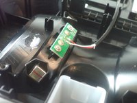
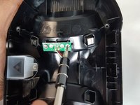
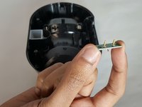
    • Remove the two screws (5.21mm Phillips head) on the board on the top half of the transmitter that is holding the charging pins.

  4. Turtle Beach Elite 800 Transmitter Contact Pins Replacement: crwdns2935265:04crwdnd2935265:01crwdnd2935265:03crwdne2935265:0 Turtle Beach Elite 800 Transmitter Contact Pins Replacement: crwdns2935265:04crwdnd2935265:02crwdnd2935265:03crwdne2935265:0 Turtle Beach Elite 800 Transmitter Contact Pins Replacement: crwdns2935265:04crwdnd2935265:03crwdnd2935265:03crwdne2935265:0
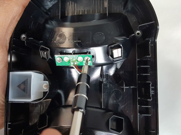
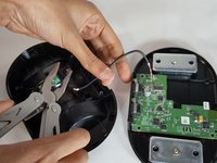
    • Once the screws are removed, desolder the two wires from the board, and then remove it, and the charging pins with it.

    • Take extreme caution when dealing with a soldering iron. Refer to the desoldering guide for tips.

    • Note that for the purposes of this guide we simply clipped the wires connected to the board holding the charging pins.

crwdns2915888:0crwdne2915888:0

To reassemble your device, follow these instructions in reverse order.

Johnny Lofton

crwdns2935283:001/18/17crwdne2935283:0

861 crwdns2915208:0crwdne2915208:0

crwdns2935297:05crwdne2935297:0

crwdns2915084:0crwdne2915084:0

Arkansas State University, Team 1-5, Chamberlain Spring 2017 crwdns2935289:0Arkansas State University, Team 1-5, Chamberlain Spring 2017crwdne2935289:0

ARSU-CHAMBERLAIN-S17S1G5

crwdns2931471:03crwdne2931471:0

crwdns2935297:010crwdne2935297:0

crwdns2917034:0crwdne2917034:0

Where did you get the new contact pins?

Kenneth Roberts - crwdns2934203:0crwdne2934203:0

crwdns2917038:0crwdne2917038:0

crwdns2936625:0crwdne2936625:0:

crwdns2936751:024crwdne2936751:0 1

crwdns2936753:07crwdne2936753:0 1

crwdns2936753:030crwdne2936753:0 8

crwdns2942667:0crwdne2942667:0 1,546