crwdns2915892:0crwdne2915892:0
If the screen/digitizer on your Trio Stealth-10 is no longer functioning, replacement isn't difficult and this guide will give you the step by step procedure to do so.
crwdns2942213:0crwdne2942213:0
-
-
To remove the back panel, you will need to use a plastic opening tool and slowly separate the back panel from the device.
-
-
-
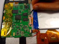
Solder the connections off for the battery.
-
-
crwdns2935267:0crwdne2935267:0Tweezers$4.99
-
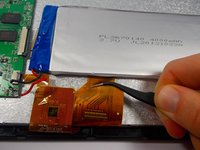
Disconnect the screen/digitizer connection. Use tweezers and pull each grey end of the connection until there is a small gap between the grey and white on the connector to the motherboard. The connection should be easily removable.
-
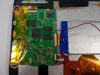
Pull the cable away and clear from under the battery to avoid damage to the connection.
-
-
-
Pry battery up from adhesive. Use a type of adhesive remover. Nail polish remover works well.
-
-
-
Next you must solder off the wires that connect the speaker to the motherboard.
-
-
-
Next you will need to remove the two screws attached to the speaker. If you have a 54 bit Driver Kit use the Philips Head 0 (or PH 0) head to remove the two 4mm screws.
-
-
-
-
Next use your PH 0 to remove the two 4mm screws to detach the camera support fixture.
-
-
-
Disconnect the camera from the mother board. Use a spudger and lift the grey latch until it is facing up then pull out the connection for the cameras.
-
-
-
Remove the first layer of tape above camera cable connection slowly.
-
-
-
Remove the second layer of tape above camera cable connection gently and remove the cameras from the device.
-
-
-
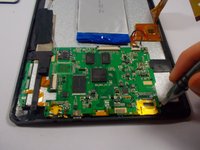
Use your spudger to disconnect the screen/digitizer connection from the motherboard.
-
-
crwdns2935267:0crwdne2935267:0Tweezers$4.99
-
Use a pair of tweezers to grasp the screen/digitizer connection gently and remove each accordingly.
-
-
-
Grasp the EDC tape with your tweezers and lift it off gently from the motherboard and set aside to be reused.
-
-
-
Use a Phillips #0 to unscrew the 4mm screws from the motherboard fixture.
-
-
-
Be sure that all the connections to the motherboard are disconnected. Proceed to remove the motherboard by slowly tilting it away from you and then lifting it straight up.
-
-
-
Remove all disconnected components and remove screen/digitizer.
-


To reassemble your device, follow these instructions in reverse order.
To reassemble your device, follow these instructions in reverse order.
crwdns2935221:0crwdne2935221:0
crwdns2935229:03crwdne2935229:0

crwdns2915084:0crwdne2915084:0

UMass Dartmouth, Team 1-4, Miles Fall 2015 crwdns2935289:0UMass Dartmouth, Team 1-4, Miles Fall 2015crwdne2935289:0
UMASSD-MILES-F15S1G4
crwdns2931471:03crwdne2931471:0
crwdns2935297:012crwdne2935297:0
crwdns2947412:02crwdne2947412:0
I can fix them like its no $@$* I want every tool to fixs them I use tool but I want the right ones I like making $$$$$
I want all smart TV that are broke I like working on them I have for many years