crwdns2915892:0crwdne2915892:0
This is a guide on how to replace a Tivax MiTraveler 10Q-8 Motherboard. When using this tablet and you notice it might be running slower or not at all, it might be time to replace the Motherboard. The Motherboard is important for the distribution of electricity through the device. Replacement requires soldering and the device's battery to be removed. If needed review How To Solder and Desolder Connections.
crwdns2942213:0crwdne2942213:0
-
-
With the device face down, slide the charging port cover off on the left side of device.
-
-
-
Remove the 2.9 mm screw from the charging port using a Phillips #000 screwdriver.
-
-
-
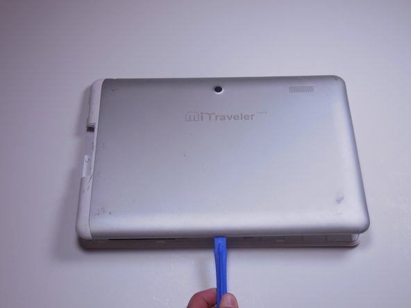
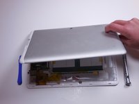
To pry the back plate off, use the plastic opening tool between the back plate and front plate; start at the headphone jack.
-
-
-
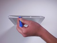
Move around the device with the plastic opening tool, pushing down to release the back plate from clips.
-
-
-
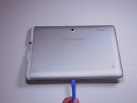
Once you’ve moved around the whole device with the plastic opening tool, the back plate will completely release from the rest of the device.
-
-
-
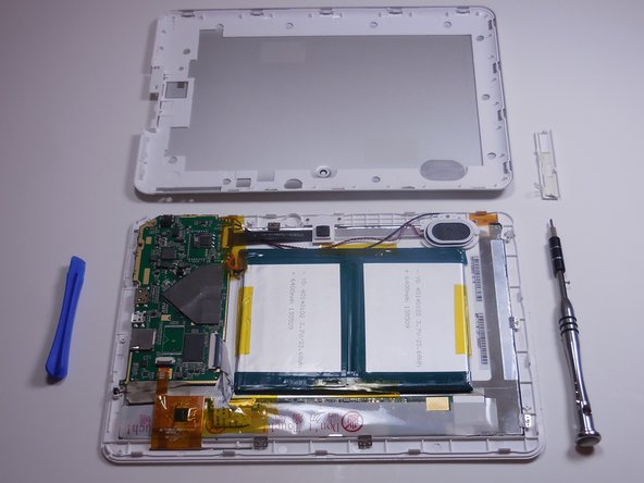
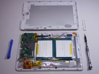
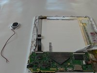
The battery rests flat on the inside surface of the tablet. It is a rectangular shape and has blue and yellow tape.
-
-
-
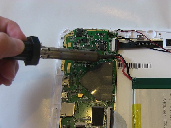
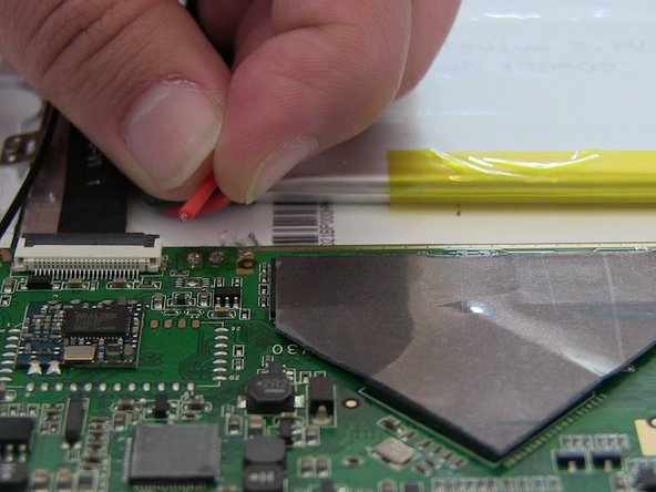
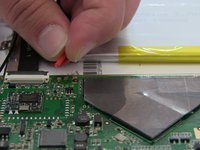
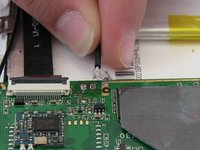
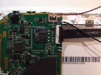
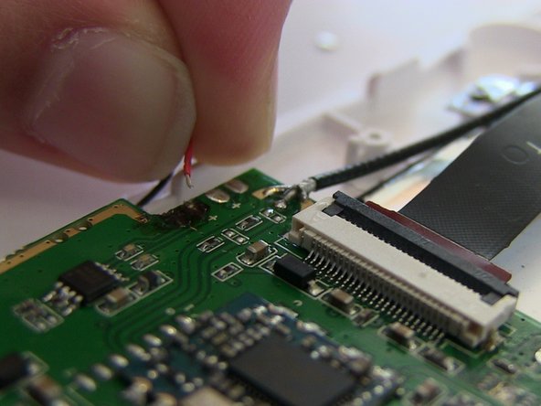
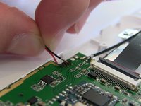
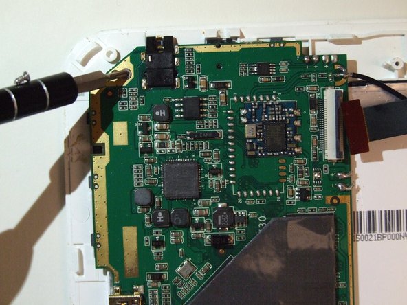
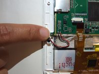
Two wires, one red and one black, which run from the motherboard to the battery, need to be desoldered from the motherboard.
-
Review how to solder here.
-
-
-
-
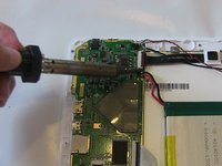
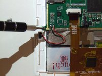
Work the soldering gun on the red wire where it is connected to the motherboard. It should release from the motherboard.
-
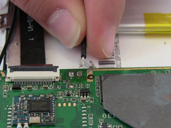
Work the soldering gun on the black wire where it is connected to the motherboard. It will release from the motherboard.
-
-
-
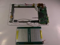
Once both wires have been desoldered, remove the battery from the device.
-
-
-
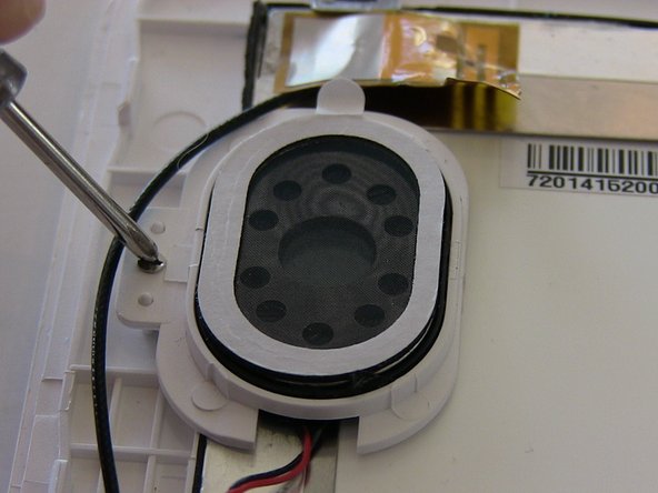
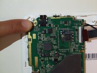
With the face of the device down, locate the speaker in the upper right corner.
-
-
-
Remove the 3.9 mm screw holding the speaker in place using a Phillips #000 screwdriver.
-
-
-
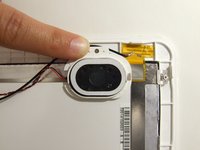
The speaker will be connected to two wires; one black and one red. Both run to the motherboard.
-
The wires will need to be soldered off the motherboard.
-
Locate where both wires are soldered to the motherboard.
-
Review How to Solder Here
-
-
-
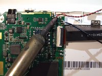
Work the iron where the red wire is soldered.
-
The wire will release from the motherboard.
-
-
-
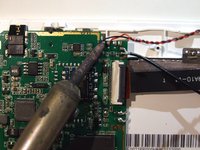
Work the iron where the black wire is soldered.
-
The black wire will release from the motherboard.
-
After both wires have been soldered off, the speaker will release from the device.
-
-
-
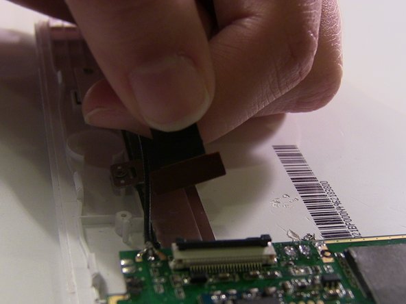
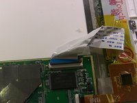
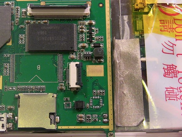
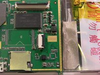
To remove the black ribbon connector, flip the black portion of the connector upward.
-
Pull on the ribbon to remove from the connector.
-
-
-
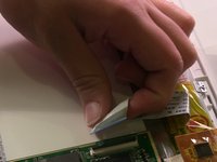
Remove the white ribbon connector from the motherboard.
-
-
-
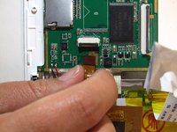
Remove the orange ribbon connector from the motherboard.
-
-
-
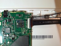
Locate a 2.88 mm Phillips head screw in the upper right hand corner of the mother board.
-
Use a #00 screw driver with the PH000 screw head to remove the screw.
-
-
-
Locate a 2.88 mm Phillips head screw on the lower left hand corner.
-
Use the #00 screw driver with the PH000 screw head to remove the screw.
-
-
-
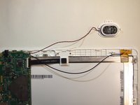
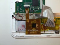
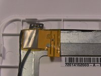
Locate a strip of gold tape, which holds it to the device, on the bottom of the motherboard.
-
-
-
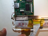
On the upper right hand corner of the device, a black wire connects to the device and runs to a strip of orange tape.
-
Remove the tape that holds the wire down.
-
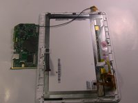
Remove the motherboard from the device.
-


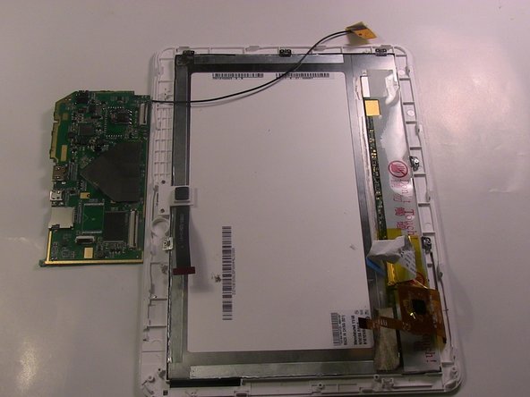
To reassemble your device, follow these instructions in reverse order.
To reassemble your device, follow these instructions in reverse order.
crwdns2915084:0crwdne2915084:0

Colorado Springs, Team 4-3, Panko Spring 2015 crwdns2935289:0Colorado Springs, Team 4-3, Panko Spring 2015crwdne2935289:0
UCCS-PANKO-S15S4G3
crwdns2931471:03crwdne2931471:0
crwdns2935297:010crwdne2935297:0