crwdns2931315:0crwdnd2931315:0crwdne2931315:0
crwdns2942213:0crwdne2942213:0
-
crwdns2935201:0crwdne2935201:0 crwdns2935203:0crwdne2935203:0
-
Remove a Torx security screw from the rear of the iron.
-
-
crwdns2935201:0crwdne2935201:0 crwdns2935203:0crwdne2935203:0
-
Using a nylon spudger, or with care a small flat screwdriver, ease the rear cover away from the main body of the iron on both sides, starting at the top near the cable entry.
-
Once the rear cover starts to come away you can increase the gap created by inserting the spudger a little further down.
-
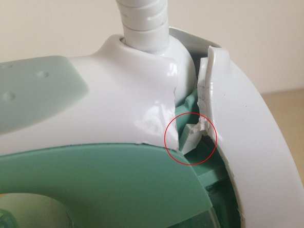
Note the tab on the rear cover shown in the 3rd photo which was holding the rear cover in place. On reassembly this can't be re-inserted without lifting the top cover (see Step 7 later).
-
-
crwdns2935201:0crwdne2935201:0 crwdns2935203:0crwdne2935203:0
-
You can now remove the mains cord inlet half-ball from its socket and the cord from the strain relief S-bend.
-
If all you need to do is replace the mains cord you can now do so. Ensure you use heat-resistant cable of the same current carrying capacity.
-
-
crwdns2935201:0crwdne2935201:0 crwdns2935203:0crwdne2935203:0
-
Remove the two steam buttons. These just pull out. To get the first one out, press the other so you can grip the one you're trying to remove.
-
-
-
crwdns2935201:0crwdne2935201:0 crwdns2935203:0crwdne2935203:0
-
Remove the anti-calc valve in front of the steam buttons.
-
-
crwdns2935201:0crwdne2935201:0 crwdns2935203:0crwdne2935203:0
-
Remove a Torx security screw which was hidden by the steam buttons.
-
-
crwdns2935201:0crwdne2935201:0 crwdns2935203:0crwdne2935203:0
-
Whilst lifting the rear of the top cover with one hand, release two clips, one each side, which retain it.
-
If you went no further than removing the rear cover and want to replace it, you have to perform this step before you can re-insert its tabs.
-
-
crwdns2935201:0crwdne2935201:0 crwdns2935203:0crwdne2935203:0
-
Push the top cover in the direction shown by the arrow in order to release the four tabs shown in the second photo.
-
List the top cover off.
-
-
crwdns2935201:0crwdne2935201:0 crwdns2935203:0crwdne2935203:0
-
Remove a Torx security screw from near the front of the iron, revealed by the removal of the top cover.
-
Lift off the top of the iron.
-
-
crwdns2935201:0crwdne2935201:0 crwdns2935203:0crwdne2935203:0
-
Disconnect a linkage between the temperature control mechanism and the steam valve. You can do this by pressing one part with a small flat-blade screwdriver while supporting the other underneath. Take care as these small plastic parts could easily be broken.
-
A linkage on the other side operated by the automatic steam control simply lifts off.
-
Slide both mechanisms back as far as they will go.
-
Note that on reassembly both mechanisms and the knobs controlling them must all be in their rear-most positions to ensure they re-connect correctly.
-
-
crwdns2935201:0crwdne2935201:0 crwdns2935203:0crwdne2935203:0
-
There are 3 twisted metal tabs holding the plastic base to the sole plate assembly. Twist each with pliers to line it up with its slot.
-
You can now lift the plastic base away from the sole plate assembly.
-
-
crwdns2935201:0crwdne2935201:0 crwdns2935203:0crwdne2935203:0
-
You can now inspect the thermostat. This comprises a bimetallic strip which opens or closes a pair of contacts. The contacts may need cleaning as a result of ingress of water.
-
You can clean the contacts with switch cleaner fluid (available in an aerosol) and a small piece of fine emery paper. Ensure that the contacts snap open and closed when you apply light pressure to one side or the other of the bimetallic strip.
-
On this iron, perhaps slightly unusually, there is a second pair of normally closed contacts which may have suffered corrosion. If you know what these are for, please leave a comment on this Instructable. My guess is that they are a safety cut-out to prevent overheating and fire if the iron is left standing flat while switched on.
-
Identify the connections to the element and test the resistance between them with a multimeter. It should be around 30 ohms (this iron is rated at 240V 2KW).
-


crwdns2935221:0crwdne2935221:0
crwdns2935229:020crwdne2935229:0

crwdns2915084:0crwdne2915084:0

Restart Project crwdns2935289:0Restart Projectcrwdne2935289:0
Community
crwdns2931471:018crwdne2931471:0
crwdns2935297:0502crwdne2935297:0
crwdns2944067:04crwdne2944067:0
THX a lot! I would never have found the screws! :)
BR
Michael
Very good guide. The steps were the same on my Tefal Avantis 120.
I believe that you should change your guide. If you remove the top-cover first, you don’t brake the plastic tabs.
Looks good. I do wish you had specified the size of the security torx. I have a set of bits, but the hole is to small for the sleeve on my driver. I was hoping to find the size to only purchase what I needed. I rather suspect that T-fal would not use a different size for every model iron.
Unfortunately the short security bits you get in a set are of limited use in many such situations for reasons you’ve discovered. I suggested to iFixit a while back that they develop a hex screwdriver extension with a very thin sleeve but they were unable to come up with a way of making it sufficiently strong whilst as thin as you need. I’m sorry I didn’t record the size of Torx bit, but at the end of the day, a set of long bits or individual screwdrivers is a very worthwhile investment.