crwdns2915892:0crwdne2915892:0
This guide replaces the ChatMix potentiometer for the SteelSeries Arctis 7+ (2021). This is a simple fix but does require careful soldering. The replacement potentiometer is a 10KOhm thumbwheel which has pins that are closely matched to the original in the headset and a wheel that is similar in size. Note that the wheel is much flatter than the original. This fix may be applicable for the volume potentiometer but this has not been tested.
crwdns2942213:0crwdne2942213:0
-
-
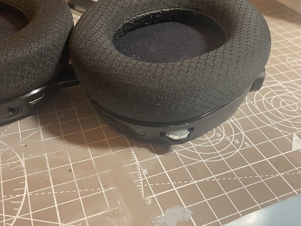
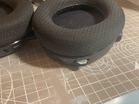
Pad is held on by a loop around the outside
-
Grabbing one side of the pad and pulling on it should release it
-
-
-
3x size 0 philips screw hold the right ear speaker in place
-
No screws are hidden under the labels
-
-
-
3x size 0 screws hold the Right Ear PCB in place
-
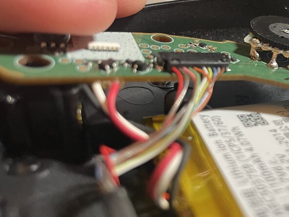
Pull the PCB out by pulling up and away from the headphones
-
The ChatMix Knob may catch on the housing and require a bit of wiggling to get it out
-
Be careful to not break the speaker and connection wires
-
-
-
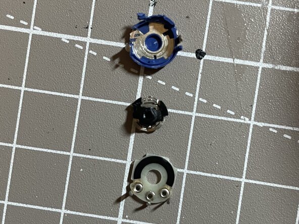
1x size 0 philips screw holds the existing ChatMix potentiometer Knob
-
Remove the screw and knob. They can be thrown out since we will not need them
-
-
-
-
Remove the existing potentiometer by cutting each pin on the top side of the PCB (The side with all of the components)
-
You can try to de-solder each pin with a solder sucker or solder braid but I did not have success with this
-
Be careful to not de-solder any of the other components or damage the PCB traces
-
It is ok to leave solder inside of the PCB holes
-
-
-
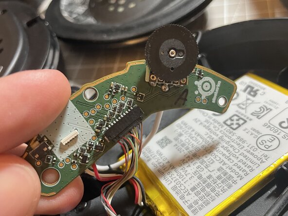
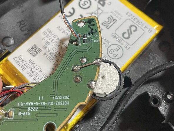
The far left, far right, and middle pins are what we want to keep
-
The middle left and middle right pins should be cut off
-
The ground pins on the case can optionally be cut to prevent any snagging
-
-
-
This is the hardest step
-
The placement of the holes on the PCB and the potentiometer will not allow for the potentiometer to fall into the PCB holes
-
Due to the different pin placements, the left and right pins should be on top of the left/right holes while the middle pin will be on the back edge of the middle hole
-
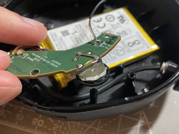
Be careful of the angle of the potentiometer. It should be close to parallel with the PCB
-
It is easiest to solder the left and right pins first
-
-
-
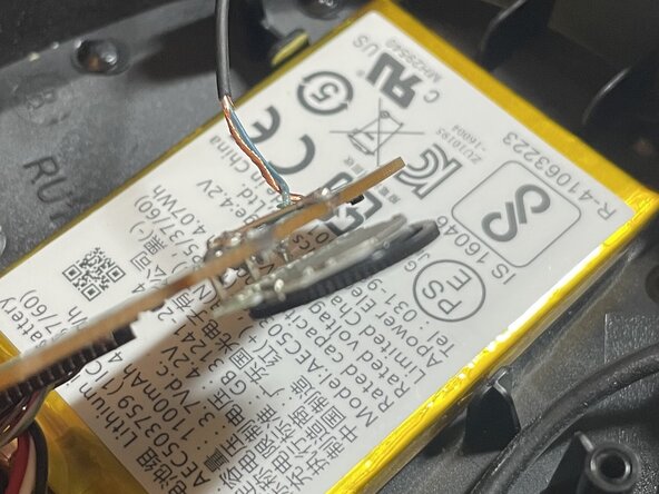
The old potentiometer had a unconventional pinout which requires us to connect these two pins
-
Be careful that the wire does not touch other pins
-
-
-
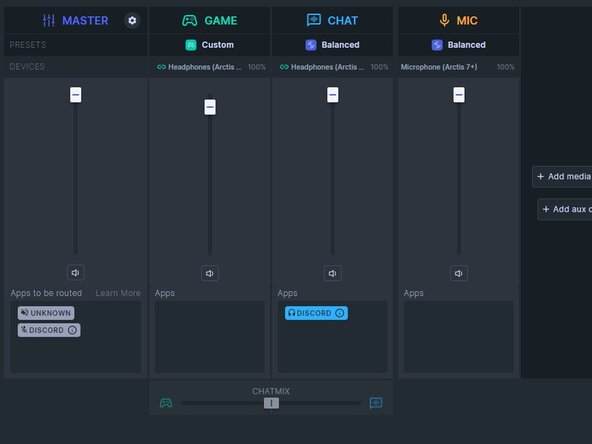
Check that the SteelSeries GG ChatMix bar moves left and right as you turn the potentiometer
-
Be careful to not twist the potentiometer too hard as it could break the solder joints
-
If you're not seeing the ChatMix bar move, restart SteelSeries GG before checking your solder joints
-
-
-
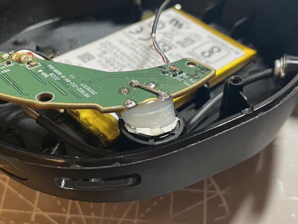
This removes stress from the solder joints
-
Be careful to only put hot glue on the back of the metal part of the potentiometer so that it can still spin freely
-
Too much hot glue can prevent the PCB from fitting in the housing. If you place too much, remove it with a knife until the PCB fits
-
Wait for the hot glue to cool before testing the potentiometer in SteelSeries GG. Make sure the solder joints have held
-
-
-
Be careful when putting the PCB back in that you don't force the potentiometer
-
3 size 0 Philips screws for the PCB
-
3 size 0 Philips screws for the Speaker
-
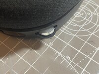
(Optional) Add a small dab of hot glue on the outside of the wheel of the potentiometer when the ChatMix is in the middle to know when the wheel is in the middle
-